When you click on links to various merchants on this site and make a purchase, this can result in this site earning a commission. Affiliate programs and affiliations include, but are not limited to, the eBay Partner Network.
Tech / General EngineIs your car making a strange sound or won't start? Thinking of adding power with a new combination? Need other technical information or engine specific advice? Don't see another board for your problem? Post it here!
I need some help identifying the sensor and connector below. It came from the thermostat housing of an 83 305 with a carburetor and I think it’s a coolant temp sensor but I cannot find a similar one online? Can I switch to a different pigtail and sensor? Thanks in advance for any help!
CTS (Coolant Temperature Sensor) is a two wire connector coming from the ECM harness to the water neck (I assume you have either the L69 or LG4 motor?).
The lead for the coolant fan switch is a single wire. The wire is grounded through the switch itself which completes the circuit to engage the relay. With the car in 'run' you should be able to ground the lead and witness the radiator fan running ... provided everything else works as it should of course.
Thanks! This definitely looks close and I might be missing something with the explication but mine does have two wires. One yellow and one black. Do I ground the wire elsewhere? I was able to find a photo of it on the motor.
I'd expect the original sending unit in the water neck to be the 2 wire coolant temp sensor as noted by the quote from naf earlier. Probably because someone previously botched it. What exactly they did, IDK without tearing into it myself. If your car is a mechanical fan then it didn't need a coolant fan switch.
Yellow and black usually denotes a temp sensor for the ECM. (usually green for other stuff) You could probe the sensor with a multi meter and read the ohms looking for change with the coolant temperature going up and down. If it reads out ok you'll just need a new connector spliced in.
The Hyper-Link that was Posted for the Electrical Connector is incorrect... (same as a Knock Sensor Connector).
I am not familiar with a Two Wire/ Two Terminal Electrical Connector for that Thermostatic Switch...
The Digital Database that Delphi has, does not include that Connector.
Late 1970s and Early 1980s Connectors that were less common were not scanned into the Digital Database.
I am going to look through some of my Paper-Files for that Connector.
Also there is a Single-Wire Connector that looks very similar:
Some Aftermarket Companies reproduce these Pig-Tails... Packard Electrical/ Delphi has not produced those Connector Parts in a long time.
GM/ ACDelco did sell the Pig-Tails for a while longer (after Delphi stopped production of the actual Connector Parts).
Post some more Images with the Connector cleaned up, and try to show me where both Wires insert.
That looks like the same connector used for the brakes in the proportioning valve. Did they use that for other sensors/switches/sending units other than brakes? Honestly asking to learn.
Thanks for the reply’s! So I seem to have a little update but maybe not? I have looked in an old shop manual and have found a description of the parts in question with confirmation that it is a coolant sensor but no part specific part number that I can find… with that being said if I can’t find an exact replacement would I be good to wire in the equivalent? I’m good at swapping out parts with the exact same thing but this is a little past me 🤣 hahaha.
Published GM Service Manuals do not include Part Numbers... as Part Numbers are very often changed/ updated.
But I am glad to see the Service Information!
Is that an 82 or 83 Manual? ...or something else?
In terms of operation, it is a 5V Sensor (Two Wire) that operates from 0.50V to 4.50V.
I wish I have seen a Two Wire version of that Connector.
There must be Two separate Contacts in the Connector... it is hard to see from the Images, where the Second Contact is.
According to a Friend of mine (who also worked for GM, but earlier than I did) had some information for me.
He is into Corvettes and not Third-Gens...
There were of course Cross-Fire Injection Corvettes.
Here is an Image of the same Connector and Sensor from a Corvette:
He said that the TPI version of these Parts will do just fine.
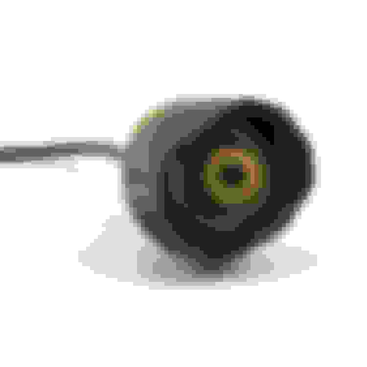
Vortec, thanks for the info! I can see why GM stopped using these types of plugs, mine crumpled over the years exposing the wires. Here’s a look at the contacts on the connector, you can see what has been lost to time.
Edit: the previous photo was from the GM 83 Camaro shop manual!
Last edited by Mrossevelt; 12-04-2021 at 07:09 PM.
Reason: Adding more
The Single Wire Connector has a Contact inside the very center bore of the Connector.
The Two Wire version that you have...
appears to have the same center Contact, and then the Second Contact is a Sleeve on the outside of the center bore of the Connector.
Does that sound correct, based on what you can see in person, holding the Connector?
The original CTS on those older carb cars was a sort of "coaxial" arrangement. It had the center pin that the yellow wire went to, and a sort of "ring" for the black/wht (ground side) one. It wasn't a particularly spectacular design to begin with, but the factory installation 100% positively assured rapid failure. They wrapped it in some sort of special slimy weird black gooey electrical tape unlike anything I've ever seen anywhere else, that if you touched it you'd have black gook on your hands for days; you had to literally soak in lacquer thinner to get it off. Whatever it was, it eventually (not a real long time, after maybe 5 yrs or so) ate the insulation off of the yellow and black wires just like in that photo, causing them to short together, which gives the ECM the indication of very high temperature; and even if you fixed those by taping them up or whatever, it ate the plastic body part of the connector as well, at which point the whole thing would fall to pieces and lose connection altogether, which mimics the indication of very cold temp. Virtually EVERY ONE of them would throw codes for CTS errors, which might at any time be for either of those total fail conditions. Sometimes in my car I'd find codes for BOTH conditions stored.
The solution is quite simple. ELIMINATE that stooooopid crap ONCE AND FOR ALL. In I guess it must have been around 1990, I put a later-model CTS on my 83 when I measured it and found that its electrical properties were identical to my early one whose connector had utterly disintegrated to the point it wouldn't work for more than a day or 2 at a time, except that the other had a reliable connector, that even CAME IN THE BOX with it. What a deal.
Today, that same setup is listed as the replacement for those cars.

 12-03-2021, 05:47 PM