
How to identify burnt wiring
 02-18-2016, 08:17 AM
#1
Member
Thread Starter

How to identify burnt wiring
Hello,
I've been thinking about electrics.
My car has an H4 conversion on the outer lamps, with dead inner lamps (still sealed beam) and I've been wondering about upgrading all lamps to Halogen and upgrading the harness (one's on order, cheaper than I could fudge it myself).
And then I looked at this in my engine bay:
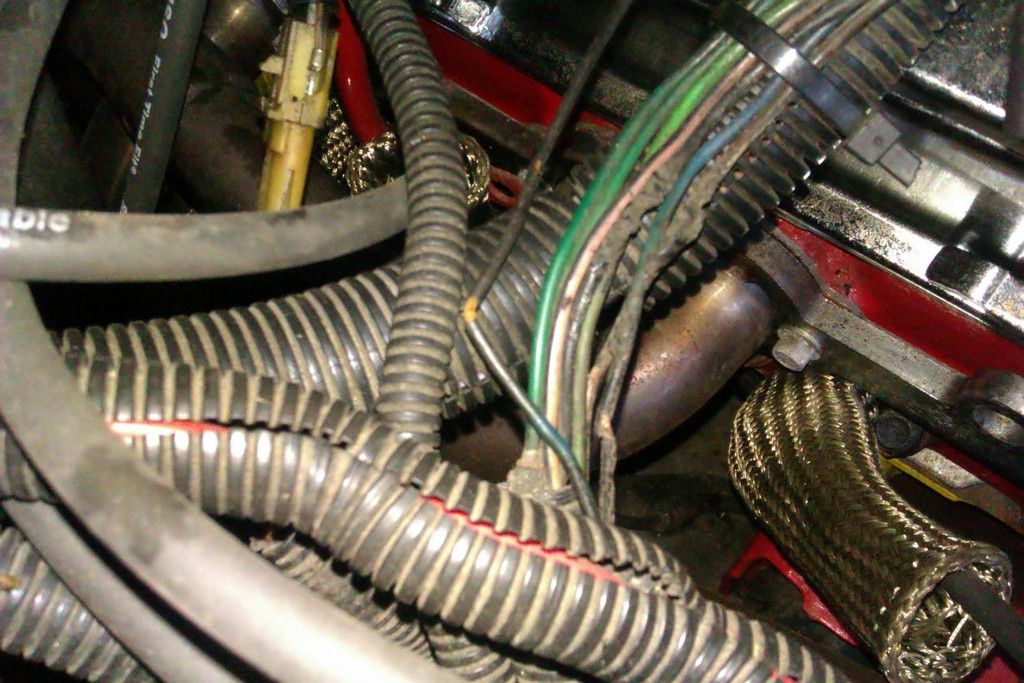
to be honest I've been ignoring it, but it's probably time I stopped and tried to work out why that wiring's fried.
I don't think they melted on the headers, as the insulation looks like it was burnt/melted by the wires themselves. It also makes me suspicious that they're outside the ducting and possibly the result of someone else's bodge. The blue wire with the big kink isn't connected to anything. The A/C has been removed (by the PO) so I don't know if that's relevant.
Can anyone offer me any tips or pointers on how to identify these wires? The only blown fuse I know of is for the vapour-lock pump, but I don't know if that's relevant. The only other source of potential over-loaded wiring (that I know of) are the two H4 lamps...
Sorry if it's a rather basic question, but I'm no auto-electrician! I may well take it to a specialist, but perhaps it would be better to know what I'm dealing with before attempting to drive it any great distance...
Many thanks for any help or advice!
N
 02-19-2016, 02:18 AM
#2
Supreme Member

Join Date: Apr 2006
Location: Northern, CA
Posts: 4,482
Likes: 0
Received 9 Likes
on
9 Posts
Car: 1989 Iroc-Z Camaro
Engine: TBI,5.0
Transmission: Automatic 700R4
Axle/Gears: Eaton Posi,3.42,LPW Ultimate Cover
Re: How to identify burnt wiring
I suggest at the very least a Chilton's Manual for your car.(about $25.00 at the local auto parts store)
Information from this site is very nice but the manual will help you to start to understand some of the things you will want to know about the car.
There pretty good reading . You will be surprised at how much you will pick up quickly combining this site and the manual.
It has diagrams showing wiring and tells you the colors of the wires involved. You will need a "magnifying Glass" to read them though.
Also being able to use a "digital Multimeter" will be very helpful as you go along. Nothing fancy, just a basic one like this will do.
= http://www.harborfreight.com/7-funct...ter-90899.html
Grab one of these too.
Just hook it to a ground and probe for 12v. Very nice.
= http://www.harborfreight.com/612v-ci...ead-61652.html
Last edited by Ron U.S.M.C.; 02-19-2016 at 02:41 AM.
02-19-2016, 08:07 AM
#3
Member
Thread Starter
Re: How to identify burnt wiring
Thanks for the hints Ron,
I do have a Chilton's manual, but it doesn't have any circuit diagrams. My Haynes does, though.
I do have a basic multimeter, but that's good point about picking up a circuit tester.
I guess I'll just have to go through it all as logically as possible and see if I can work out what those wires are! I was hoping someone might be able to give me a pointer about what the particular bit of trunking does so I can narrow down my search. It appears from the bulkhead at one end, and then goes into the wing (fender!) at the other end I think. It contains a few connectors that were related to the A/C, which has been removed and the plugs left dangling...
Cheers,
Neil
02-20-2016, 08:00 AM
#4
Member
Thread Starter
Re: How to identify burnt wiring
Got a chance to look at the car again earlier, the melted wiring appears to run to this relay at the front of the car:

Does anyone know what this is? Is it the fan relay? The wiring dives back into the engine bay though, and didn't seem to connect to the fan... That's the radiator on the left of the photo, and the battery at the bottom.
I'm hunting through wiring diagrams, but they don't really tell you where stuff is!
03-09-2016, 07:30 AM
#5
Member
Thread Starter
Re: How to identify burnt wiring
Finally got to check the car at the weekend, and discovered that relay isn't for the coolant fan. I discovered the broken fan switch connector dangling in the engine bay and grounding it resulted in a spinning fan and a click from the driver's side firewall.
So, what's this relay? Can anyone help? I'm hunting through diagrams and kinda clutching at straws. Is this the fog light relay? (Although they work - I can check for a click next time I'm at the car). Could this be a relay for the in tank vapour-lock pump? (That blows a fuse each time I turn the car on...)
Any advice or suggestions at all would be welcome!
Cheers,
N
03-09-2016, 08:10 PM
#6
Supreme Member
iTrader: (4)
Join Date: Sep 2004
Location: MN
Posts: 2,069
Likes: 0
Received 3 Likes
on
3 Posts
Car: 85 SC, 86 Berlinetta
Engine: V6, V8
Transmission: 700r4, 700r4
Re: How to identify burnt wiring
I kind of like to post in one shot so here goes.
The wire ducting doesn't do much other than make things look nicer. Here in the US we call it wire loom and it's easily to find and is inexpensive. I'm not sure if it's something that GM does specifically, but I've seen heat shielding wrapped around the loom to help protect the wiring as well. That may actually be useful in the header area.
To be honest, I will challenge you on the wiring being affected by the headers.
I could be wrong or others can disagree, I'm not a mech, I just dabble with these cars from time to time.
I agree with Ron on a lot of what he posted but I might recommend this if you can afford it: http://www.helminc.com/helm/homepage.asp
Hopefully someone will chime in on the relay, but this may help in the meantime:
http://www.austinthirdgen.org/?pid=19
I hope that helps and was clear enough. I don't have a lot of time but wanted to offer some info & ideas to help you along with the time I do have. -Good luck!
The wire ducting doesn't do much other than make things look nicer. Here in the US we call it wire loom and it's easily to find and is inexpensive. I'm not sure if it's something that GM does specifically, but I've seen heat shielding wrapped around the loom to help protect the wiring as well. That may actually be useful in the header area.
To be honest, I will challenge you on the wiring being affected by the headers.
- For one it's pretty common for the heat to affect wiring is similar situations.
- Two, headers would cause damage to appear on the outside of the coating vs. from the inside with the outer coating still looking like new (with the exception of bubbling up). [High amperage shorts melting the wire from the inside will heat up the wire along the length, the coating may melt off of the wire, or burn away completely, or come apart at a point of highest resistance. Also sometimes at a connector, or more likely at a protection point such as a fuse or fusible link. The wire may also be crunchy inside, definitely not shiny anymore. IF/when you do remove it you can inspect it from the inside and if there is evidence it was an actual short (IMO) you need to find the cause of it and correct it.]
- Three, it's unlikely you would have multiple shorts in the different circuits that just happen to be cabled together.
- Four, it would be highly unlikely for shorted wire to fail simultaneously in the same stretch/area of cabling.
I could be wrong or others can disagree, I'm not a mech, I just dabble with these cars from time to time.
- If it is possible, I would try to get a replacement harness and go from there. From where you're posting from I'm going to assume that isn't an economical option. One thing you could do is buy automotive specific wiring (at the correct gauge/s) and take apart the connectors to reuse. Most GM connectors actually break down pretty easily. You could splice, but that would be my last choice. If you do splice, it's a good idea to offset the connection points so the area doesn't bulk up, and also isn't as likely to short out against each other. Also study different splice techniques and if you want to solder or crimp.
- If the H4's (Halogen?) draw more current you may want to increase the gauge or switch to LEDs or something.
- IIRC, once you remove the plastic inner fender from underneath the wiring is easily accessible. Please do not splice in this area though.
- If you're worried about corrosion, you can tape over the unused connectors after adding a bit of dielectric grease.
I agree with Ron on a lot of what he posted but I might recommend this if you can afford it: http://www.helminc.com/helm/homepage.asp
Hopefully someone will chime in on the relay, but this may help in the meantime:
http://www.austinthirdgen.org/?pid=19
I hope that helps and was clear enough. I don't have a lot of time but wanted to offer some info & ideas to help you along with the time I do have. -Good luck!
03-10-2016, 04:04 PM
#7
Member
Thread Starter
Re: How to identify burnt wiring
Thanks for the advice Scorpner. I'm pretty new to automotive wiring, so I don't yet have the experience to recognise how different problems appear.
I think you might be right that the damage to the wiring might not be due to a short - it did occur to me that it was lucky/weird that the damage had occurred in such a visible and accessible place. Perhaps the wiring simply got caught up and damaged when the previous owner reinstalled the engine...
I would be keen to find out what that relay is - the connectors to it look pretty ropey and I couldn't take it apart suggesting it might be a little melted inside. I've found a few good links to austinthirdgen, but unfortunately I don't seem to be able to access the website; perhaps because I'm in the UK.
Thanks for the link to the service manuals - they're out of stock for my car, but I'll keep an eye on it.
I've bought an uprated loom for the H4/H1 halogen lights, which takes a feed directly from the battery and uses the existing connector as a switch. Thanks for the tip to access the wiring from underneath - I was wondering the best way to get to it!
Cheers,
N
Trending Topics
03-10-2016, 07:30 PM
#8
Supreme Member
iTrader: (4)
Join Date: Sep 2004
Location: MN
Posts: 2,069
Likes: 0
Received 3 Likes
on
3 Posts
Car: 85 SC, 86 Berlinetta
Engine: V6, V8
Transmission: 700r4, 700r4
Re: How to identify burnt wiring
You're very welcome, hopefully a few words can get you up to speed in little time.
Yes, only if things were that easy to fix. lol
I think you may be right in thinking it was from the engine swap. That makes a lot of sense. I've heard of wiring getting pinched after the engine install and then shorting out when the battery was hooked back up.
There should be a tab (or tabs) that hold the relay box together. With age the plastic can be brittle, so it may not go back together as easily. You should be able to find out more about the relays, how to test, etc., by searching Google. If you do open it up you should be able to see right away if it's damaged inside. My guess if it was hot enough to melt inside, that the plastic would be warped enough to notice.
If you're lucky, you may also be able to buy a manual on Ebay. I've bought a year off for one Camaro, but I already knew that the years were similar. (Edit: Actually with your 1985, I would avoid '84 as there were major changes. 1986 may work if you're not picky and/or you get a deal on it. ) I forgot to mention that Helms has sales every once in a while too.
Oh, it sounds like a decent upgrade on the lights then.
Last edited by Scorpner; 03-10-2016 at 07:36 PM.
03-11-2016, 07:52 AM
#9
Member
Thread Starter
Re: How to identify burnt wiring
thanks for the advice!
I have tried to open that relay, but only really put as much force as wouldn't risk breaking it. I don't want to do that - at least not until I know what it is!
I'll keep an eye out for those shop manuals - it would be very handy. The Haynes manual is rather short of information at times, sadly.
What did you mean by 'don't splice in this area' with regards to the headlights? the 12v supply cable on my conversion kit isn't long enough to reach my kill switch, so I was going to solder in an extra length of wire to make up the difference. Will there be an issue with soldering in a 12V wire? I realise it might increase resistance in the wire.
Actually, is connected the power supply to the kill switch necessary? I'd like to be able to cut power, as opposed to wire directly to the battery terminal. Is there another viable 12v source in that area that I could use instead? I'm not sure I want to go straight from the alternator, but I have heard mention of a battery junction box down by the battery. I'm not sure my car has one though...
Many thanks!
N
03-13-2016, 11:09 AM
#10
Supreme Member
iTrader: (4)
Join Date: Sep 2004
Location: MN
Posts: 2,069
Likes: 0
Received 3 Likes
on
3 Posts
Car: 85 SC, 86 Berlinetta
Engine: V6, V8
Transmission: 700r4, 700r4
Re: How to identify burnt wiring
You're welcome.
The outer case of a relay will come off but sometimes they don't stay together afterwards due to the age of the plastic (either from breaking from brittleness or deformation). I don't want to scare you but instead, make you aware on the assumption that's the only one you have. Typically there a re small tabs that you need to move to release the case from the bottom part. Below are a few links to show you the insides, how they work, & how to test.
A relay is basically an electronic switch where the trigger carries a lower current/power than the circuit being controlled. Or you could think of it as a relay race where the input is “handed off” to a larger circuit. ...In a practical sense, the trigger is a simple electromagnet (see wire coil in video below), that when activated throws the switch of the higher current/power circuit. There are two wires for input(low power) and two for output(high power).
More relay videos:
Shows how they come apart (clear box).
----
On “splice area” I was referring to the engine wiring from the dash to the engine compartment. The area inside of the fender is sill subject to road water and salt, so IMO you don't want any connectors, splices or any breaches of the wiring sheath in that area. To some, it might be tempting because it's not visible, but I wouldn't do it. (Edit: I forgot to say that I mentioned the above because I'm pretty sure at least some of the damaged wires goes to that area, and that's why I was deviating from the topic of the headlights.)
For the 12v supply you can either add or use an existing junction box or connector. If you search you will find examples of this. Here is a link that Ron posted about a year ago:
https://www.thirdgen.org/forums/tech...ml#post5913969
The outer case of a relay will come off but sometimes they don't stay together afterwards due to the age of the plastic (either from breaking from brittleness or deformation). I don't want to scare you but instead, make you aware on the assumption that's the only one you have. Typically there a re small tabs that you need to move to release the case from the bottom part. Below are a few links to show you the insides, how they work, & how to test.
A relay is basically an electronic switch where the trigger carries a lower current/power than the circuit being controlled. Or you could think of it as a relay race where the input is “handed off” to a larger circuit. ...In a practical sense, the trigger is a simple electromagnet (see wire coil in video below), that when activated throws the switch of the higher current/power circuit. There are two wires for input(low power) and two for output(high power).
More relay videos:
Shows how they come apart (clear box).
On “splice area” I was referring to the engine wiring from the dash to the engine compartment. The area inside of the fender is sill subject to road water and salt, so IMO you don't want any connectors, splices or any breaches of the wiring sheath in that area. To some, it might be tempting because it's not visible, but I wouldn't do it. (Edit: I forgot to say that I mentioned the above because I'm pretty sure at least some of the damaged wires goes to that area, and that's why I was deviating from the topic of the headlights.)
For the 12v supply you can either add or use an existing junction box or connector. If you search you will find examples of this. Here is a link that Ron posted about a year ago:
https://www.thirdgen.org/forums/tech...ml#post5913969
Last edited by Scorpner; 03-16-2016 at 08:08 PM.
03-14-2016, 08:43 AM
#11
Member
Thread Starter
Re: How to identify burnt wiring
Again Scorpner, thanks for the help!
I understand the basic principles of a relay, but it's still pretty interesting to see it shown to so clearly in those videos.
I've not got much further with understanding what that relay does, but I did get around to fitting my H4 and wiring upgrade kit at the weekend. I managed to get the 12V wire to my kill switch, which is a little bit like a junction box, and does mean I can kill power to the lights along with the rest of the car.
Only problems were working out how to secure the new relays in the engine bay - there's a likely-looking hole but I'm not sure how to secure into it (a self-tapping screw pulled through... hmph.) and that I have a good, bright high-beam on all four lamps, but no low-beams... Ran out of time to do much investigating, but I'm pretty sure all the existing grounds were reinstated. Need to check if the new relays both work!
Cheers,
N
03-16-2016, 08:07 PM
#12
Supreme Member
iTrader: (4)
Join Date: Sep 2004
Location: MN
Posts: 2,069
Likes: 0
Received 3 Likes
on
3 Posts
Car: 85 SC, 86 Berlinetta
Engine: V6, V8
Transmission: 700r4, 700r4
Re: How to identify burnt wiring
You're welcome. 
I see. I wasn't sure since you mentioned having trouble taking the one apart, and I think I misread you comment about wanting to know what a relay does vs. what that particular one does. FWIW, each of the vids had something useful, the problem is they cover too much of everything else. lol
I did pull a couple to make the thread a bit easier to read.
I was going to mention that soldering the wires isn't (necessarily) going to increase resistance. But with automotive wiring, soldering is limited (by design) due to constraint motion over time. If you look over your car, stranded wiring and crimping is used over soldering and solid wire. Soldering a connector probably isn't going to be an issue, but I've seen debates over the matter.
03-18-2016, 06:06 PM
#13
Supreme Member
Re: How to identify burnt wiring
The relay looks like it would be the heavy duty, or second fan relay, based on its location. Does the car have dual fans? It could be that the PO wired the fans together to run on a single relay. This may not be good if the wiring is being overloaded by two motors. Once you have a service manual with good diagrams, you can review how the fans were originally wired and look at how that may have changed.
A relay is simply a means by which a high load device, such as a fan or fuel pump, or even headlamps, can be controlled, without having to use large gauge wire and high current switches throughout the entire control circuit. For instance, if we were to operate a fan without a relay, we would have to have a switch and wiring that could handle the load of the fan motor. Depending on location of the components and the distances between them, the wiring for this circuit may have to be very large gauge and all devices, such as whatever type of switch we use would have to be able to carry that load. In the case of something like a fuel pump, the load would be continuous, making the job of the circuit even more demanding.
By using a relay, we are able to control the high load device using much smaller wiring for most of the circuit and smaller switches. A typical relay coil draws about .5 amps. This is true even for relays that handle as much as 70 amps continuous load. This means that we can operate a 50 amp load with a circuit mostly designed for only .5 amps. Only the power supply and secondary wiring needs to actually handle the 50 amp load.
In reality, when we design a load control circuit, especially for something like headlamps or a fuel pump that will run continuously for long periods at a time, we generally spec a relay and power circuits double the capacity needed to operate the device. For instance, for a pump that draws up to 10 amps, we will use a 20 amp relay. That way the relay can safely operate the pump for any given period, without being overheated. The wiring for this circuit will also be capable of double the current load.
As far as headlights go, relays are the best way to control this load. Modern vehicles commonly use relays to control headlights. OEMs do this largely to save weight by using smaller wire and switches. On an older vehicle, it is fairly easy to install relays to control headlights. The wiring that originally powered the lamps is used to operate the relays. We use one relay for the dim lights and another for the brights. By installing relays we remove the high load of the lamps from the headlamp and dimmer switches and the factory wiring. Now these switches and wires only need to operate two .5 amp relays. The relays and the power circuits to the lamps is now a shorter distance for the current to travel from the power source to the load. Installing relays in a 30 year old headlamp circuit will restore headlamp brightness that has diminished due to voltage loss through the old wiring and switches. When upgrading to high output headlamps, relays are essential.
On my 87, I have Hella H4 dual element outer lamps and H1 brights. Altogether with brights on, I have 400 watts of headlamps. The brights are run by a 70 amp relay. The power supply for the relay comes right off the battery just 2 feet of wire away, through a fusible link. The dims are run though a 40 amp relay which is overkill, but since I used Bosch relays, the 40 amp or a 20 amp relay are the same size and share the same connector. Now, my headlamps are super bright and my headlamp and dimmer switches have it easy and will last virtually forever.
BTW, as an automotive electrician, I solder every connection, aside from factory open barrel crimp terminals, which are crimped using a special tool that reproduces the factory crimp connection. Even a quality indent crimp tool cannot produce a good enough joint to carry high current over an extended period without risk of deterioration, which will lead to resistance, voltage loss, and further damage. If you disassemble almost any factory harness, you will find all splices soldered. The solder doesn't affect flexibility of the stranded wire as the solder joint is only 1" long, and the joint is supported by loom and harness straps. When I do solder connector terminals in a solid mounted device, like a relay, I support the harness to limit movement and prevent wire fatigue and breakage. I have had great success with this repair method over many years. Of course, any wire connection, whether crimped or soldered should be sealed with sealant type heatshrink tube. The sealant keeps moisture and oxygen out of the joint to prevent corrosion.
Last edited by ASE doc; 03-18-2016 at 06:11 PM.
03-21-2016, 05:26 PM
#15
Member
Thread Starter
Re: How to identify burnt wiring
Yes, wow! Thanks for all of that - some useful info in there.
Firstly, my car has the single-fan setup so I don't think the dual-fan theory applies. Could it still be the A/C compressor relay, or is that over by the bulkhead on the driver's side?
I have installed a new wiring harness for my lights just as you described - using the existing wiring just for switching the new harness, which takes its power directly from the battery (well, kill switch). Although I'm using 30amp relays and a relatively conservative 55/65w setup.
Thank you for your comments on soldering. I just received a new connector for my fan switch, which came with a bullet connector. I do have a basic crimping tool, but I think I'll forget the bullet connector and stick with soldering.
Many thanks!
03-22-2016, 03:16 PM
#16
Supreme Member
Re: How to identify burnt wiring
The 85 doesn't have a compressor clutch relay. These early GMs didn't use a relay. It's like I explained, the entire circuit carries the load of the clutch. It's only about 2.5-3.0 amps with a healthy coil. If that relay isn't for a fan, I could only guess that it's maybe for the fog lights, or possibly the horn. If the car were here at my shop, I would use wire colors and my factory diagrams and try to identify the relay that way.
I've been using the non-insulated butt connectors for some time now. They make good contact when crimped with a good set of indent crimpers. Then I solder the joint, essentially filling the butt connector with solder. Be sure to place a section of heat shrink tube over the wire first and slide it away from the heat of the soldering.. Then, slide it in place over the joint and shrink it in place.
I really like my Snap On solder gun. It makes plenty of heat for pretty much any auto wiring. I find it works best to heat the joint til the solder just starts to flow, then release the trigger and use the residual heat in the tip to complete the joint. It was a bit pricey up front but this gun has made no less than 1,000 solder joints in the years I've owned it. It's been though a bunch of replaceable tips and it still works great.
For heat shrink I use a Dewalt heat gun with the special deflector tip designed for heat shrink tube. I've seen people use everything from cigarette lighters to mini torches for this job. I hate to scorch wiring so I use the heat gun.
03-22-2016, 06:50 PM
#17
Supreme Member
Join Date: Apr 2006
Location: Northern, CA
Posts: 4,482
Likes: 0
Received 9 Likes
on
9 Posts
Car: 1989 Iroc-Z Camaro
Engine: TBI,5.0
Transmission: Automatic 700R4
Axle/Gears: Eaton Posi,3.42,LPW Ultimate Cover
Re: How to identify burnt wiring
The relay wiring in the photo above looks as if the wires have moved back exposing them at the connection point.
Its a strange "phenomenon" that has happened to my "Fuel Pump" relay so I know what it looks like. Those bare wires could be touching each other at the connection. As long as the relay is still working as it should......
I would take this relay off and straiten the wires out so there not touching then coat theme with "liquid electrical tape".
The reason I did it that way is because the wires connected to my relay only had a few inches before they disappeared into a large wire carrying harness.
No room to cut and solder new wire and connecters on the ends.
Last edited by Ron U.S.M.C.; 03-22-2016 at 07:10 PM.
03-23-2016, 05:02 AM
#18
Member
Thread Starter
Re: How to identify burnt wiring
the wiring diagrams do show an AC compressor relay:
http://repairguide.autozone.com/znet...3f8020e211.gif
Unless, of course I'm reading that diagram wrong... It would be good news if it is, as the A/C system has been removed and that means the relay is redundant.
Thanks for the tip on the uninsulated butt connectors - they look very useful, so I'll look into using them.
Thanks also for the tip on the liquid tape - I had no idea this stuff existed! If I can confirm that wiring is redundant, I can tidy things up using this stuff to ensure no short-circuits can occur (even if the wiring is redundant). Would that be ok to simply paint the damaged wires with this stuff until I can confirm the wires needs to come out? At least that way I don't have to faff about re-soldering in lengths of unused wire, just in case!
Thanks,
Neil
03-23-2016, 10:11 AM
#19
Supreme Member
Re: How to identify burnt wiring
[QUOTE=Ron U.S.M.C.;6020063]The relay wiring in the photo above looks as if the wires have moved back exposing them at the connection point.
Its a strange "phenomenon" that has happened to my "Fuel Pump" relay so I know what it looks like. Those bare wires could be touching each other at the connection. As long as the relay is still working as it should......
I would take this relay off and straiten the wires out so there not touching then coat theme with "liquid electrical tape".
The reason I did it that way is because the wires connected to my relay only had a few inches before they disappeared into a large wire carrying harness.
No room to cut and solder new wire and connecters on the ends.[/QUOTE
In a case like that, I will release the terminals from the relay connector, install heat shrink tube over the exposed wire, and reinstall them in the connector. The liquid tape also works but heat shrink is a more durable repair.
03-23-2016, 11:53 AM
#20
Supreme Member
Re: How to identify burnt wiring
The diagram you have linked is generic, from Autozone and I wouldn't put much faith in its accuracy. Especially since there is so much variation from one engine option to the next.
If you look more closely, you will see that the AC compressor control circuit branches off according to V6 vs. V8. The relay, along with a PS pressure cut off switch, is only used on the V6.
I get my diagrams from either the factory service manual directly, All Data which reprints the factory manual, or Mitchell Pro Demand, which publishes redrawn, easier to read versions, of the factory diagrams. All three sources are generally right on. Fortunately, I have the three to compare with each other when there is a question.
The one problem I still run into is when a manufacturer makes a design change mid year and doesn't reflect the change in their published service information. This can lead me down a rabbit hole where I have to circuit trace using circuit termination and voltage testing to determine what is really going on. Huge waste of time. If I look at all my sources, including Identifix, I might find some other poor tech who has run into the same issue on that make, model and year and shares his story to save the rest of us from the same trouble. Alot like TGO.
03-24-2016, 05:28 AM
#21
Member
Thread Starter
Re: How to identify burnt wiring
Ah yes, you're quite right. That'll teach me for referring to Autozone diagrams rather than getting off my **** and at least looking in my Haynes manual!
Actually, I really ought to spring for one of those GM shop manuals. Will cost about fifty quid to get it here, but it'll be worth it. The number of times I say 'I wish I knew what it was supposed to be like!'
My car does have fog lights, but would they be operated by a relay? I only have access to the autozone diagrams at work, and they don't show anything. Also, the wiring for the foglights seems to come from the drivers side of the car and doesn't seem to be associated with this relay.
Could the relay be for the in-tank vapour-lock pump? I have no idea where the relay for that would be installed (the wiring diagrams in the vapour lock sticky don't seem to work�) and the pump doesn't seem to operate. It blows a fuse as soon as the car is switched on. I assumed that was due to a broken pump.
Thanks for all the input on this, it's really appreciated!
03-24-2016, 05:46 AM
#22
Supreme Member
iTrader: (8)
Join Date: Oct 2001
Location: Il
Posts: 11,901
Received 916 Likes
on
600 Posts
Car: 1989-92 FORMULA350 305 92 Hawkclone
Engine: 4++,350 & 305 CIs
Transmission: 700R4 4800 vig 18th700R4 t56 ZF6 T5
Axle/Gears: 3.70 9"ford alum chunk,dana44,9bolt
Re: How to identify burnt wiring
The original picture lookes like heat from the headers made the wire casing brittle, not over heating wiring.
03-24-2016, 03:20 PM
#23
Supreme Member
Re: How to identify burnt wiring
The fog lights were run through a relay. The relay on my 87 was on the LH inner fender. I don't know if the relay in your photo may have been for the in tank pump. I'll take a look at All Data and post back on that.
The Helms publishing factory manual is very good. It is the original shop service manual that we used at the dealer level. I will say though to check it carefully once you have it. The one I bought for my 87 has errors and omissions that I should have caught sooner. Never looked at things like the front suspension section, for years after buying the book. Come to find that the whole section was omitted and the prior section repeated. Should have gotten a replacement, but by the time I caught the problem, it was too late to return the book. I'm sure if I called Helms they would send me the missing pages. We had one of these books for every model of GMC and Pontiac at the dealership back in the day. Alot of paper.
EDIT: The diagram I have for the 85 CCC(carb) model in tank pump shows different wire colors to the pump relay. Is your car a TPI? Or has it been converted to carb?
Last edited by ASE doc; 03-24-2016 at 03:24 PM.
03-24-2016, 03:26 PM
#24
Supreme Member
Re: How to identify burnt wiring
Can you take a close look and tell me what wire colors go to the relay? It's hard to tell for sure from the photo.
03-26-2016, 06:37 PM
#25
Member
Thread Starter
Re: How to identify burnt wiring
Well, I finally wrestled with that connector bravely enough to get it apart and then played a game of 'let's see what still works'.
It's a fog light relay.
Does anyone know if this is stock, or another aftermarket addition? Anyhow, I know I need to make good the wiring somehow.
Thanks to everyone for their help and suggestions, it's been incredibly useful. I've a bottle of liquid tape and a GM dealer service manual on order!
It's a fog light relay.
Does anyone know if this is stock, or another aftermarket addition? Anyhow, I know I need to make good the wiring somehow.
Thanks to everyone for their help and suggestions, it's been incredibly useful. I've a bottle of liquid tape and a GM dealer service manual on order!
03-28-2016, 04:01 PM
#26
Supreme Member
Re: How to identify burnt wiring
I wondered if it was for the fog lights. The fog lights were almost an after thought and there's no accounting for where the relay was located. I would say that it certainly looks to be factory installed, judging by the zip pins attaching it to the body. It may even have been installed at the dealership using a factory provided install kit.
My car's fog lights are long gone. In their place is ram air intake ducts.
My car's fog lights are long gone. In their place is ram air intake ducts.
03-29-2016, 03:57 PM
#27
Member
Thread Starter
Re: How to identify burnt wiring
I wondered if it was for the fog lights. The fog lights were almost an after thought and there's no accounting for where the relay was located. I would say that it certainly looks to be factory installed, judging by the zip pins attaching it to the body. It may even have been installed at the dealership using a factory provided install kit.
My car's fog lights are long gone. In their place is ram air intake ducts.
My car's fog lights are long gone. In their place is ram air intake ducts.
Ram air ducts sound nice - I do have the original dual-snorkel air filter housing, albeit without the hoses to above the headlights. However I'd worry about intakes set down that low; I live in the UK and sometimes have to ford through very deep puddles!
03-29-2016, 06:53 PM
#28
Supreme Member
Re: How to identify burnt wiring
Ah, the random location of the relay would explain why no one could easily identify it simply by where it is. It would also explain its slightly sketchy fixings - it's held in place by a couple of plastic panel poppers.
I live in the UK and sometimes have to ford through very deep puddles!
I live in the UK and sometimes have to ford through very deep puddles!
03-29-2016, 11:11 PM
#29
Supreme Member
Join Date: Apr 2006
Location: Northern, CA
Posts: 4,482
Likes: 0
Received 9 Likes
on
9 Posts
Car: 1989 Iroc-Z Camaro
Engine: TBI,5.0
Transmission: Automatic 700R4
Axle/Gears: Eaton Posi,3.42,LPW Ultimate Cover
Re: How to identify burnt wiring
ASE doc,
(In a case like that, I will release the terminals from the relay connector, install heat shrink tube over the exposed wire, and reinstall them in the connector. The liquid tape also works but heat shrink is a more durable repair.)
Good idea......
Thanks
The liquid tape is still nice to have around.
03-30-2016, 06:01 PM
#30
Supreme Member
Re: How to identify burnt wiring
ASE doc,
(In a case like that, I will release the terminals from the relay connector, install heat shrink tube over the exposed wire, and reinstall them in the connector. The liquid tape also works but heat shrink is a more durable repair.)
Good idea......
Thanks
The liquid tape is still nice to have around.
(In a case like that, I will release the terminals from the relay connector, install heat shrink tube over the exposed wire, and reinstall them in the connector. The liquid tape also works but heat shrink is a more durable repair.)
Good idea......
Thanks
The liquid tape is still nice to have around.

Thread
Thread Starter
Forum
Replies
Last Post