C4 IRS Planning
 08-22-2011, 03:47 PM
#1
Senior Member
Thread Starter
iTrader: (2)
Join Date: May 2008
Posts: 433
Likes: 0
Received 0 Likes
on
0 Posts
C4 IRS Planning
Been following 1MeanZ & FlyDoc's threads.
But as luck would have it, the week I saw FlyDoc’s thread, I saw an ad on craigslist close to my house. I ended up with this for $400 delivered.

I have read all of the available threads but still have a few questions I would like to plan for. The car was almost ready for wiring & paint before I switched plans on the rear suspensions. You may find that some of the questions is towards 1MeanZ. But as we all may agree , he wrote the bible on C4 IRS swap in a 3rd gen.
Here are some of the questions / confusion I have;
I already brought my wheels 2 years ago for a lot. So I want to keep them. They are 17X9.5. I don’t have tires for them yet and don’t have funds for them now. The IRS is on some 16” spares. I think they are 135/60/16. I didn’t take anything off the IRS except for the transverse spring & C-beam.
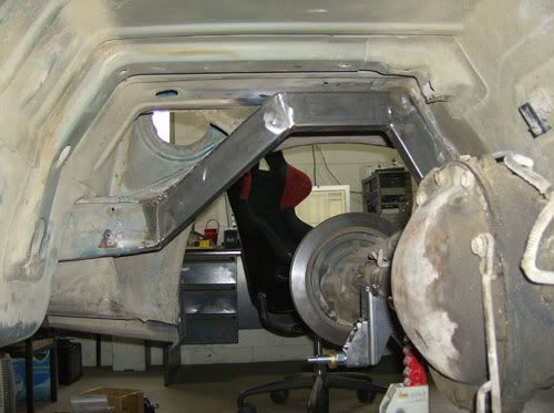
1. I want to position the IRS hubs correctly in the wheel well. I am guessing this would position the Batwing mount and the 2 pairs of trailing arm correctly. Can I get some idea’s how to do this? My car is stripped to the bare chassis, so I cannot think of a way to get an accurate datum?
3. Also would I need to get the wheel & tire combo to correctly do this at this time?
4. How high did you end up placing your batwing ears? From pictures I see that the driver side is level with the 3-hole panhard mount on the frame rail?
5. Batwing Mount: I am thinking of using some preformed frame rails similar to the ones from competition engineering, tying the front and rear to the stock frame rails and then using a shackle mount to attach the batwing ears, instead if flattening the spring picket area and dropping a mount from there like you did. Something like this photo below. Any concerns with this approach? My concern is clearance of the shock hanging from the stock location.
6. Trailing arm mounts: My understanding is that at ride height, the half shaft’s are parallel to the ground and both the trailing arms (dog bones) are also parallel to the ground. Then at squat (compression-up), the dog bones will slightly angle down and when the suspension is hanging t (compression-down), the dog bones will angle up. Is this a correct understanding?
8. Also can you give me an idea how in a stock corvette, what adjustment on the IRS is done to adjust the forward and aft location of the wheel in the wheel well?
9. What is the total adjustability (+/- 2-5 inch??) for each of these tubular control arms you got to replace the dog bones? This is what I am referring to :

10. You also said that shortening the top dog bones would not be good in keeping the corvette IRS specs. Can you explain that? My thinking is the stock dog bones don’t have any adjustability. So as long as the angle is correct (shorten both the top & bottom proportionally) it should be fine. I think it’s not as simple as that??
11. Locating Drive train: The stock 3rd gen rear is offset to one side for the torque arm mount. The IRS C-beam mount is on the opposite side. So how did you end up centering your pinion left to right?
12. Looks like you had the tranny up high in the tunnel and had to raise the tunnel sheet metal. Was this because you wanted the IRS pumpkin as high inside the chassis as possible or what it because of the particular transmission you used?
13. I have a LS1/T56. You think it would be a good idea to center the engine, the T56 pinion and the IRS pinion and get rid of the inherent offset the stock 3rd gens have on the pass side (due to torque arm on drive side ) or is this somehow taken care of in the 3rd gen sub-frame design.I am thinking of slotting the holes on the mount & tranny X-member. Bad idea?
14. Bump stop: How much of squat should I need for the IRS suspension to work properly? I know it depends on how much tire I have in the wheel well. But this kind of ties back into how high inside the chassis the pumpkin needs to be located. Would it be enough if the half shafts can be limited to 5 degrees (inches??) up from parallel? I think in your thread somewhere u said you limited the compression-up by the amount of shock travel before it was stopped by the bump stop.
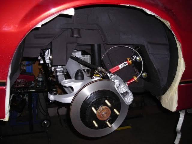
15. Do you know where the stock corvette bump stop would contact the hub assembly? Is it very close to where the stock corvette sway bar is mounted? General area where you finger is in this picture?

But as luck would have it, the week I saw FlyDoc’s thread, I saw an ad on craigslist close to my house. I ended up with this for $400 delivered.
I have read all of the available threads but still have a few questions I would like to plan for. The car was almost ready for wiring & paint before I switched plans on the rear suspensions. You may find that some of the questions is towards 1MeanZ. But as we all may agree , he wrote the bible on C4 IRS swap in a 3rd gen.
Here are some of the questions / confusion I have;
I already brought my wheels 2 years ago for a lot. So I want to keep them. They are 17X9.5. I don’t have tires for them yet and don’t have funds for them now. The IRS is on some 16” spares. I think they are 135/60/16. I didn’t take anything off the IRS except for the transverse spring & C-beam.
1. I want to position the IRS hubs correctly in the wheel well. I am guessing this would position the Batwing mount and the 2 pairs of trailing arm correctly. Can I get some idea’s how to do this? My car is stripped to the bare chassis, so I cannot think of a way to get an accurate datum?
3. Also would I need to get the wheel & tire combo to correctly do this at this time?
4. How high did you end up placing your batwing ears? From pictures I see that the driver side is level with the 3-hole panhard mount on the frame rail?
5. Batwing Mount: I am thinking of using some preformed frame rails similar to the ones from competition engineering, tying the front and rear to the stock frame rails and then using a shackle mount to attach the batwing ears, instead if flattening the spring picket area and dropping a mount from there like you did. Something like this photo below. Any concerns with this approach? My concern is clearance of the shock hanging from the stock location.
6. Trailing arm mounts: My understanding is that at ride height, the half shaft’s are parallel to the ground and both the trailing arms (dog bones) are also parallel to the ground. Then at squat (compression-up), the dog bones will slightly angle down and when the suspension is hanging t (compression-down), the dog bones will angle up. Is this a correct understanding?
8. Also can you give me an idea how in a stock corvette, what adjustment on the IRS is done to adjust the forward and aft location of the wheel in the wheel well?
9. What is the total adjustability (+/- 2-5 inch??) for each of these tubular control arms you got to replace the dog bones? This is what I am referring to :
10. You also said that shortening the top dog bones would not be good in keeping the corvette IRS specs. Can you explain that? My thinking is the stock dog bones don’t have any adjustability. So as long as the angle is correct (shorten both the top & bottom proportionally) it should be fine. I think it’s not as simple as that??
11. Locating Drive train: The stock 3rd gen rear is offset to one side for the torque arm mount. The IRS C-beam mount is on the opposite side. So how did you end up centering your pinion left to right?
12. Looks like you had the tranny up high in the tunnel and had to raise the tunnel sheet metal. Was this because you wanted the IRS pumpkin as high inside the chassis as possible or what it because of the particular transmission you used?
13. I have a LS1/T56. You think it would be a good idea to center the engine, the T56 pinion and the IRS pinion and get rid of the inherent offset the stock 3rd gens have on the pass side (due to torque arm on drive side ) or is this somehow taken care of in the 3rd gen sub-frame design.I am thinking of slotting the holes on the mount & tranny X-member. Bad idea?
14. Bump stop: How much of squat should I need for the IRS suspension to work properly? I know it depends on how much tire I have in the wheel well. But this kind of ties back into how high inside the chassis the pumpkin needs to be located. Would it be enough if the half shafts can be limited to 5 degrees (inches??) up from parallel? I think in your thread somewhere u said you limited the compression-up by the amount of shock travel before it was stopped by the bump stop.
15. Do you know where the stock corvette bump stop would contact the hub assembly? Is it very close to where the stock corvette sway bar is mounted? General area where you finger is in this picture?
 08-23-2011, 02:19 PM
#2
Re: C4 IRS Planning
hey man, I'm posting this publicly because I feel bad about neglecting your PMs and feel I should take it on the chin for that. With my '91 TA getting smashed on vacation, all the turbulence that caused, and we just had our baby girl yesterday so I'm sure you can understand how busy it's been. I'm now somewhat a man of leisure, let me know when is a good call this week.
With that said I'll take to answering your questions one at a time below. I'm just sitting in the hospital room now and mom and baby are sleeping so I've got a bit.
With that said I'll take to answering your questions one at a time below. I'm just sitting in the hospital room now and mom and baby are sleeping so I've got a bit.
08-23-2011, 02:29 PM
#3
Re: C4 IRS Planning
I'm going to respond to each question individually so the questions and my response can be individually quoted or responded to in the future without having a huge chain of quoted info that is not pertinent to each issue.
When I bolted my "datum" to the car, I just measured an equal distance off the rear hubs and bolted it to the bottom of the rear ground effects. It could have been clamped there or tack welded to the chassis. With the rear end out, just measure from your rear control arm mount holes. The key is to get the datum square in the car like the rear axle was, measuring from the control arm holes should work fine.
1. [/FONT]I want to position the IRS hubs correctly in the wheel well. I am guessing this would position the Batwing mount and the 2 pairs of trailing arm correctly. Can I get some idea’s how to do this? My car is stripped to the bare chassis, so I cannot think of a way to get an accurate datum?
Last edited by 1MeanZ; 08-23-2011 at 02:33 PM.
08-23-2011, 02:32 PM
#4
Re: C4 IRS Planning
Must have forgot #2? LOL
If I understand this question correctly you're still referring to positioning the diff front to rear. The wheels and tires won't help with that, they can move and flop all around and will be nothing but a hinderance.
If I understand this question correctly you're still referring to positioning the diff front to rear. The wheels and tires won't help with that, they can move and flop all around and will be nothing but a hinderance.
08-23-2011, 02:37 PM
#5
Re: C4 IRS Planning
I mounted the batwing ears about 1/2" below the fuel tank. I wanted to get the diff as high in the car as possible so I could lower the car and still have correct geometry. I already have what some believe to be the dreaded fuel pump access, so mating up close to the tank was no worry for me because I can get the fuel pump from the top side.
08-23-2011, 02:50 PM
#6
Re: C4 IRS Planning
5. Batwing Mount: I am thinking of using some preformed frame rails similar to the ones from competition engineering, tying the front and rear to the stock frame rails and then using a shackle mount to attach the batwing ears, instead if flattening the spring pocket area and dropping a mount from there like you did. Something like this photo below. Any concerns with this approach? My concern is clearance of the shock hanging from the stock location.
08-23-2011, 02:55 PM
#7
Re: C4 IRS Planning
6. Trailing arm mounts: My understanding is that at ride height, the half shaft’s are parallel to the ground and both the trailing arms (dog bones) are also parallel to the ground. Then at squat (compression-up), the dog bones will slightly angle down and when the suspension is hanging t (compression-down), the dog bones will angle up. Is this a correct understanding?
Last edited by 1MeanZ; 08-23-2011 at 03:12 PM.
Trending Topics
08-23-2011, 03:00 PM
#8
Re: C4 IRS Planning
http://www.banskimotorsports.com/C4_...#Trailing_Arms
08-23-2011, 03:08 PM
#9
Re: C4 IRS Planning
Can't see the pix yet but can answer anyway. I have adjustable camber rods and adjustable trailing arms on the car. i did it to get rid of the rubber bushings in the stock pieces. All of my parts use the same rod end and I believe they have 1-1.5" TOTAL adjustment which is more than enough if you've measured correctly and got the rear in the right spot.
 08-23-2011, 03:33 PM
#10
Re: C4 IRS Planning
10. You also said that shortening the top dog bones would not be good in keeping the corvette IRS specs. Can you explain that? My thinking is the stock dog bones don’t have any adjustability. So as long as the angle is correct (shorten both the top & bottom proportionally) it should be fine. I think it’s not as simple as that??
08-23-2011, 03:43 PM
#11
Re: C4 IRS Planning
I located my diff off the faces of the output yokes on the diff. I hung a weighted string from the top of each fender lip and measured from the string to the yokes.
08-23-2011, 03:48 PM
#12
Re: C4 IRS Planning
Raising the trans had to happen somewhat by accident. I had the rear diff installed with the pinion 2* nose up, so I wanted the output yoke of the trans to be 2* nose down. With my TKO600 swap the trans was facing 6* nose down so I had to raise the trans up until it was 2* down. This required me to raise the trans tunnel to make room for the trans, but also gave me awesome clearance for my dual exhaust.
08-23-2011, 03:54 PM
#13
Re: C4 IRS Planning
The 2 forward arms on the IRS make a virtual swing arm that's longer than those 2, an effective way to get a long swing arm in a confined space. however, shortening them does make the swing arm IC move quite a bit and this has an effect on what little anti squat there is w/ an IRS. Don't make them too short.
As for the diff, yes the diff case itself is offset in the live axle the pinion is not centered either. The 2 axle tubes are not equal length. The same however is true for the IRS. The whole drivetrain is always offset to the drivers side in most cars, a corvette stock has an offset of about 1" on the engine and a little less on the pinion, giving you a driveshaft angle in the horizontal plane upon that in the vertical plane.
As long as you center the location of the batwing it will be OK. The fact that the C beam is located on the passenger side is not a big problem. You won't be able to use it anywaym unless you run an automatic and swap the tailpiece for a Corvette one (or a 4+_3 or ZF s6-40 which are both pretty unlikely swaps) and even then, you would need to custom fab the c beam or just simply fab a pinion mount.
08-23-2011, 04:05 PM
#14
Re: C4 IRS Planning
13. I have a LS1/T56. You think it would be a good idea to center the engine, the T56 pinion and the IRS pinion and get rid of the inherent offset the stock 3rd gens have on the pass side (due to torque arm on drive side ) or is this somehow taken care of in the 3rd gen sub-frame design.I am thinking of slotting the holes on the mount & tranny X-member. Bad idea?
08-23-2011, 04:09 PM
#15
Re: C4 IRS Planning
14. Bump stop: How much of squat should I need for the IRS suspension to work properly? I know it depends on how much tire I have in the wheel well. But this kind of ties back into how high inside the chassis the pumpkin needs to be located. Would it be enough if the half shafts can be limited to 5 degrees (inches??) up from parallel? I think in your thread somewhere u said you limited the compression-up by the amount of shock travel before it was stopped by the bump stop.
08-23-2011, 04:11 PM
#16
Re: C4 IRS Planning
I do not know where the stock corvette bump stop is located. They may even have rubber bumpers around the shock shaft that do the job. I do not own a corvette, nor have I worked on many of them. This is where Twin Turbo may have to bail me out with a picture or description. I'm sure he knows this answer.
08-23-2011, 05:27 PM
#17
Member


Join Date: May 2008
Location: Planet Oahu Hawaii
Posts: 300
Likes: 0
Received 3 Likes
on
3 Posts
Car: 92 RS
Engine: 94 LT1 383
Transmission: T56-6 Speed
Axle/Gears: posi, 3.26:1,
Re: C4 IRS Planning
in the answers to the questions, I agree with 1MeanZ.
there is a few changes in the way that I located the bat-wing in my build
1st I would have used this chases dimensions to make sure my car was straight, which it is. then I would have used it to locate all my mounting points. my biggest Fu@* up was that my trailing arms are not quite in the same position (for-aft) R is 1/8 forward, L is 1/4 back. not optimal but was able to correct with adjustable control arms.
08-23-2011, 05:32 PM
#18
Member
Join Date: May 2008
Location: Planet Oahu Hawaii
Posts: 300
Likes: 0
Received 3 Likes
on
3 Posts
Car: 92 RS
Engine: 94 LT1 383
Transmission: T56-6 Speed
Axle/Gears: posi, 3.26:1,
Re: C4 IRS Planning
the next thing that I would have changed, is that I would have drilled the spot welds and remove the chassis support in one pice, it would have made it easier to put back in and trim to fit.
rather than removing a part of it. as the way I did it
you can see in photo
rather than removing a part of it. as the way I did it
you can see in photo
08-23-2011, 05:51 PM
#19
Member
Join Date: May 2008
Location: Planet Oahu Hawaii
Posts: 300
Likes: 0
Received 3 Likes
on
3 Posts
Car: 92 RS
Engine: 94 LT1 383
Transmission: T56-6 Speed
Axle/Gears: posi, 3.26:1,
Re: C4 IRS Planning
the way I mounted the control arm mount / bracket in my opinion is spot on for strength and least intrusive on space.
Oh did I just open myself to lots of sharp shooters.
it is made out of 2x4 1/4" tubing, in at a angle of 66* which is what I figured the * of the stock mount and it slid wright in to the stock trailing arm point. then I used the same material to make my sub frame connectors maybe over-kill. then 1/4" plate to tie it all to gather in the rear.
I have not put in Bub stops or a sway bar, but will happen. (not tell Jan, I'm going to the main land).
08-23-2011, 07:49 PM
#20
Junior Member

Join Date: May 2009
Posts: 49
Likes: 0
Received 0 Likes
on
0 Posts
Re: C4 IRS Planning
Been following 1MeanZ & FlyDoc's threads.
1. I want to position the IRS hubs correctly in the wheel well. I am guessing this would position the Batwing mount and the 2 pairs of trailing arm correctly. Can I get some idea’s how to do this? My car is stripped to the bare chassis, so I cannot think of a way to get an accurate datum?
1. I want to position the IRS hubs correctly in the wheel well. I am guessing this would position the Batwing mount and the 2 pairs of trailing arm correctly. Can I get some idea’s how to do this? My car is stripped to the bare chassis, so I cannot think of a way to get an accurate datum?

Last edited by lees02ws6; 08-23-2011 at 07:53 PM.
08-23-2011, 08:00 PM
#21
Junior Member
Join Date: May 2009
Posts: 49
Likes: 0
Received 0 Likes
on
0 Posts
Re: C4 IRS Planning
The half shafts and camber rods are not paralell, nor are they supposed to be. At ride height, my half shafts are horizontal, the camber rods are lower on the outboard side. As the suspension compresses you get a slight amount of negative camber gain, which is a good thing for cornering. We can get into that in more detail if thats needed. I want to keep these responses concise and and directly answer the questions. Also, the trailing arms are not parallel, both have a slight down angle at ride height, I have a diagram of the factory angles that I think I posted in my build thread. I'll post it here when I can get out of the hospital and can access photobucket.
 08-23-2011, 08:31 PM
#22
Member
Join Date: May 2008
Location: Planet Oahu Hawaii
Posts: 300
Likes: 0
Received 3 Likes
on
3 Posts
Car: 92 RS
Engine: 94 LT1 383
Transmission: T56-6 Speed
Axle/Gears: posi, 3.26:1,
Re: C4 IRS Planning
here is 1MeanZ's anti-squat and wheel-rate charts.
As for centering you wheels with your chassis striped, I would use a jig like lees02ws6 posted center it front to rear, as for rider height use this Tire size calculator http://www.miata.net/garage/tirecalc.html to find the diameter of the tire that you are planning on using then use that measurement to determine your ride height.
As for centering you wheels with your chassis striped, I would use a jig like lees02ws6 posted center it front to rear, as for rider height use this Tire size calculator http://www.miata.net/garage/tirecalc.html to find the diameter of the tire that you are planning on using then use that measurement to determine your ride height.
08-23-2011, 08:44 PM
#23
Junior Member
Join Date: May 2009
Posts: 49
Likes: 0
Received 0 Likes
on
0 Posts
Re: C4 IRS Planning
I do not know where the stock corvette bump stop is located. They may even have rubber bumpers around the shock shaft that do the job. I do not own a corvette, nor have I worked on many of them. This is where Twin Turbo may have to bail me out with a picture or description. I'm sure he knows this answer.
 08-24-2011, 04:15 PM
#24
Senior Member
Thread Starter
iTrader: (2)
Join Date: May 2008
Posts: 433
Likes: 0
Received 0 Likes
on
0 Posts
Re: C4 IRS Planning
hey man, I'm posting this publicly because I feel bad about neglecting your PMs and feel I should take it on the chin for that. With my '91 TA getting smashed on vacation, all the turbulence that caused, and we just had our baby girl yesterday so I'm sure you can understand how busy it's been. I'm now somewhat a man of leisure, let me know when is a good call this week.
With that said I'll take to answering your questions one at a time below. I'm just sitting in the hospital room now and mom and baby are sleeping so I've got a bit.
With that said I'll take to answering your questions one at a time below. I'm just sitting in the hospital room now and mom and baby are sleeping so I've got a bit.
Thanks again for taking the time to answer the questions. And that goes for everybody on this thread. I am going to take some time to gleam over this information.

Thread
Thread Starter
Forum
Replies
Last Post