When you click on links to various merchants on this site and make a purchase, this can result in this site earning a commission. Affiliate programs and affiliations include, but are not limited to, the eBay Partner Network.
This is my personal project for street and an Open Track day on occasion. The entire suspension is from a '92 Corvette, including the ABS. The K-member is custom built because nothing else would work short of setting the engine back 6" (I didn't want that). The rear seat area is still intact and as usable as is was originally. All of thr geometry was either retained or improved upon with a CAD program. Getting ready to install the engine, so we'll know soon if I'm right.
I'm telling you now, if you mass produced that K member setup you'd be a millionaire overnight. In my opinion that trumps a coil over setup all day everyday.
I had to section the framerails in order for this to work, so the k-member really isn't a normal bolt in. This is the 4th version that I made, the first 2 I was still trying to use the mono leaf. This is so much better in many ways.
I'm serious man, even with the cutting and welding that would need to be done this is insane. When you're all done you HAVE to do either a write up or try to market this. It's amazing.
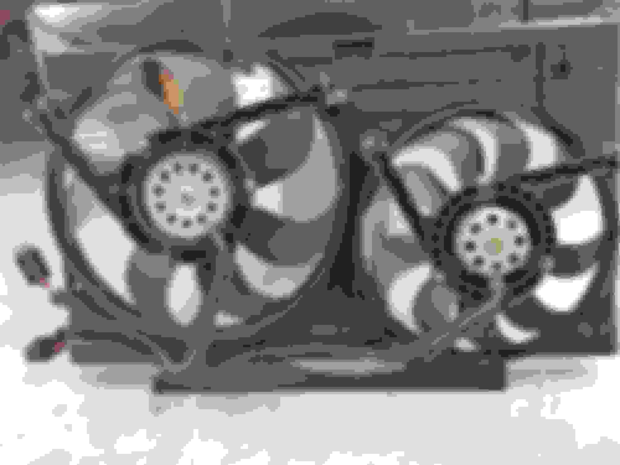
Stock fan shroud and GTO fans assembly become one piece
Engine oil cooler and power steering cooler bracket mounted ahead of radiator
Engine from the left side
Let me know if anyone is interested in more detailed pictures, I'll remove some of the components photograph them. I'm really bad at documenting my work.
I'll take some detailed pictures and post tomorrow (10/8/17). I used a universal kit modified the brackets and the firewall to fit. I also had to modify the stock ducting which I'll explain with pictures.
Vintage air with the dash in position
The original ducting with extensive modifcations
These are the center vent inlets, 2" ABS plumbing fittings.
Close-up of the defrost duct inlet. this is the supplied Vintage air duct cut and bonded into place.
Unit installed, dash removed.
PCM mounted to the cover of the original blower fan box.
A/C and Heater plumbing in the original blower fan box.
An attempt to show the hole that was cut into the left side of the blower box for the plumbing.
Front mount bracket, it's in the shape of the Vintage piece, but with a 45 degree joggle to mate up to the dash. The stand offs are 1" .120 wall tube with rubber expansion nuts installed. There are 6 of these, 4 on the back plate and 2 on the front.
Case drain attached to a fitting installed in the firewall. The fitting is just under the starter cable seen in the previous engine compartment pictures.
A better shot of the plumbing in the blower box.
�Any intelligent fool can make things bigger, more complex, and more violent. It takes a touch of genius � and a lot of courage to move in the opposite direction.�
― Ernst F. Schumacher
This all looks amazing, and i want to copy as much as i can! I hope to build my car at least 20% as nice as yours.
first of many questions. Wont water get into the cabin via the hose hole by the cover? I just painted that inner area on my car. I also have my firewall blocked off. So i am in a similar situation.
The blower box where the plumbing resides has a large drain hole from the factory because the original blower draws air from the cowl at the base of the windshield. the hole I cut is on the opposite side of and higher than the drain hole. Hope this answers your question.
I am sure you are correct, I just don't understand.
seems like water can still run down the windshield, into the cowl area, head towards the passenger side main drain and potentially thru the hole one of your tubes needed.
again, I am sure you have it sorted out, I just ask because I want to use that area as a bulkhead for coolant too, but can't understand how to get the lines into the cabin without it being a mess and creating a path for leaks.
any chance you could take a pic from the cowl area looking towards the main drain? Like this:
water can rush down the bottom face and splash aground on its way out
The bulkhead for the hoses are centered where the blower motor once was on the firewall. If the blower motor did not ingest water at negative pressure (sucking air into the cabin) from the cowl, the access for the hoses I made will not. I'll post some pictures tonight in order to clarify what I'm saying.
Good call Dennis, that will definitely fill the car up with water first time I wash it. I really appreciate you bringing this to my attention. Fortunately it should be an easy fix, I'll tape around the hole on the outside and use some injection foam to seal the area. As far as pre fab pictures, no I didn't document the build. There are some pictures of the tear out for the rear suspension and wheelwell tubs, but not much for the front. Again, thank you for the heads up, it's times like this is why we come on here for feedback.
Bet it feel good seeing the engine in there finally, and not to mention, having it all fit! It's coming along great. Can't wait to see more progress!
I'm actually trying to muster up the motivation to go out and chop off my passenger frame rail now and do the whole process all over again haha. And right when I was just starting to feel accomplished being done with the drivers side!
Thanks for the kind words. Yes it is the Magnum IV. Honestly, the HVAC has been one of the easier projects on this build. The most time consuming has been the wiring.
Once the frame rails are complete, the hard part will be over. After that, it's just fitting parts (and making them fit). Keep up the great work, I've been following the videos and your thread. Talk to you later.
soloc4 your car and fabrication skills are amazing! It makes my "home brewed road racer" build look like a turd. I swapped in a 4th gen z28 front suspension, steering and brakes on my build but also moved front wheels 5" forward for better weight distribution.
Like others I wish you had posted a build thread. could you possibly post a few pictures of engine to rack clearance?
Fantastic work and please keep us updated on its performance.
Dave
Here�s a good clear shot from straight on. There�s about a 1/4� gap from the oil pan.
Steven, I'm wondering if when you have a few minutes, you could take a picture or two of inside the front wheel wells where the coilover passes by the frame rail. I'm going to have to notch mine, but I'm just not sure by how much. I should probably wait until I have the coilovers, but I'm almost 100% sure it's going to need about a 3/4" deep section removed, roughly 4" wide (allowing myself some wiggle room). The springs on the ride techs are 3.5" OD which I believe is on the larger side for coilovers.
To be honest, I'm not really "cash ready" yet to dish out the big bucks on the ride techs, but notching the frame for them is essentially my next step before I can move on. I considered even removing a full inch, because my 3x3" box steel I feel is way overkill anyways. Even that small notched section being 2x3" should be plenty strong, especially with the added bracing I'll be welding in.
You consider AFCOs? I have single adjustables from my friend that sells them, he uses them on his second gen
I did, but it seems AFCO has a very limited selection of sizing. The "perfect" size that will fit my setup is still a bit smaller than the smallest one they had.
I don't know, but I think maybe you're just seeing the off the shelf stuff? Pretty sure they make all kinds of stuff. Might be worth the investigation, if it runs a lower price. The coil overs in my second gen are fairly short
Steven, I'm wondering if when you have a few minutes, you could take a picture or two of inside the front wheel wells where the coilover passes by the frame rail. I'm going to have to notch mine, but I'm just not sure by how much. I should probably wait until I have the coilovers, but I'm almost 100% sure it's going to need about a 3/4" deep section removed, roughly 4" wide (allowing myself some wiggle room). The springs on the ride techs are 3.5" OD which I believe is on the larger side for coilovers.
To be honest, I'm not really "cash ready" yet to dish out the big bucks on the ride techs, but notching the frame for them is essentially my next step before I can move on. I considered even removing a full inch, because my 3x3" box steel I feel is way overkill anyways. Even that small notched section being 2x3" should be plenty strong, especially with the added bracing I'll be welding in.
RH side, notch is 1� recessed. This is at full droop, the gap increases slightly at ride height.
W
 05-21-2016, 05:58 PM