LTX and LSX Putting LT1s, LS1s, and their variants into Third Gens is becoming more popular. This board is for those who are doing and have done the swaps so they can discuss all of their technical aspects including repairs, swap info, and performance upgrades.

LS swap wiring diagrams

Thread Tools
 
Search this Thread
 
Old 07-16-2023, 10:05 AM
  #1  
Supreme Member

Thread Starter
iTrader: (24)
 
Pocket's Avatar
 
Join Date: Jun 2005
Location: NC
Posts: 7,931
Likes: 0
Received 142 Likes on 78 Posts
Car: 91 Trans Am
Engine: LSA
Transmission: T56 AWD
Axle/Gears: 8.8 4.10
LS swap wiring diagrams

Over the years I drew up a number of diagrams to help me build harnesses. Since I am no longer doing that, it seems they would be more useful here. Bear in mind, I drew these as an aid for myself and may have an error or two. Quite a few of these are simply redrawn for clarity as most GM and Holley schematics give me eye cancer

I apologize for the poor resolution. Not everything picks up well on a screenshot. If someone wishes to convert this .DWG to a higher resolution image, please contact me

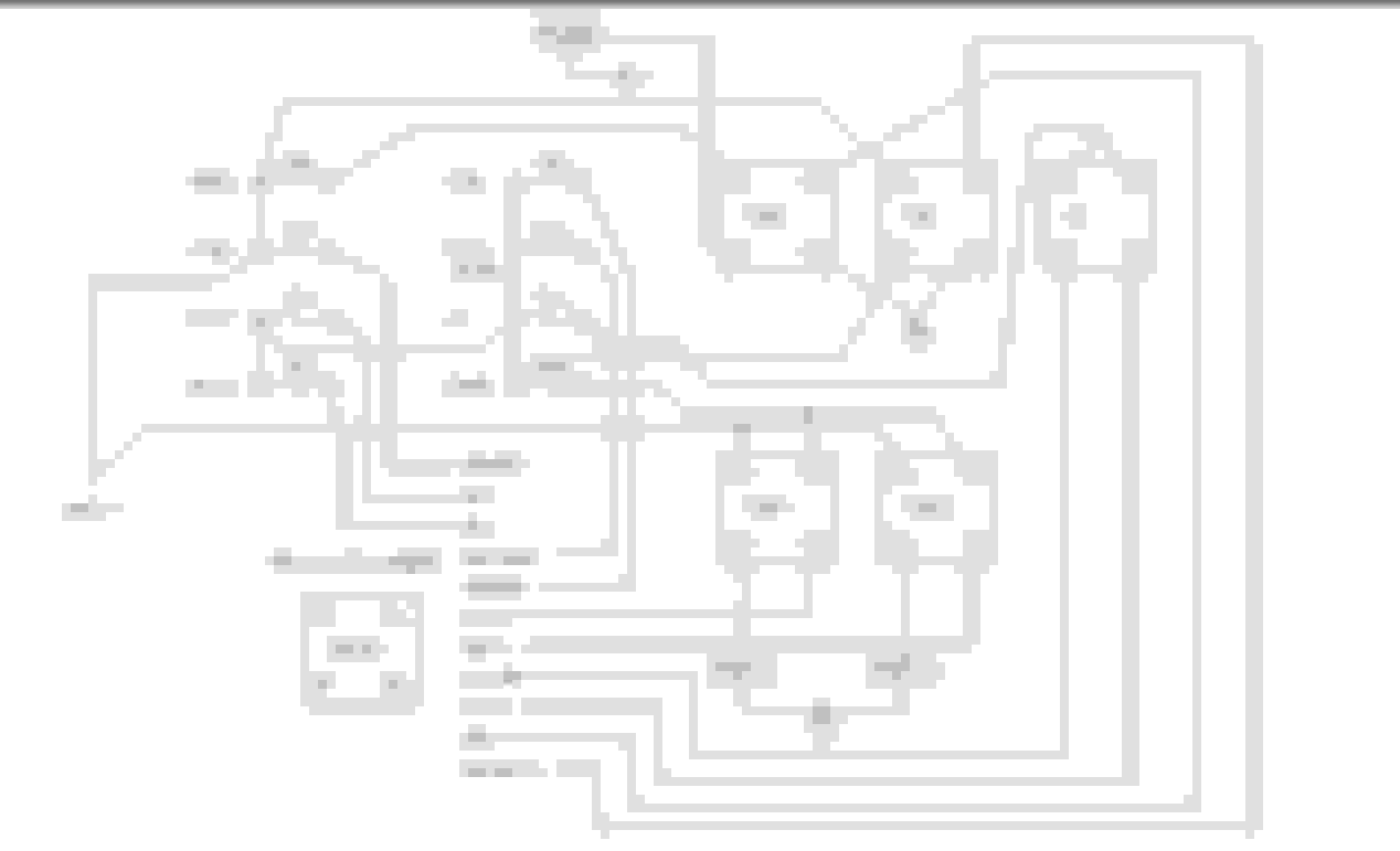
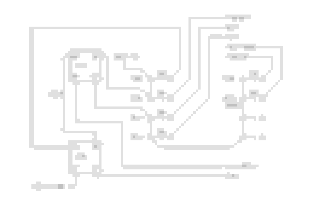
All diagrams will be first posted with an easy to read white on black, then a printer friendly black on white at the end

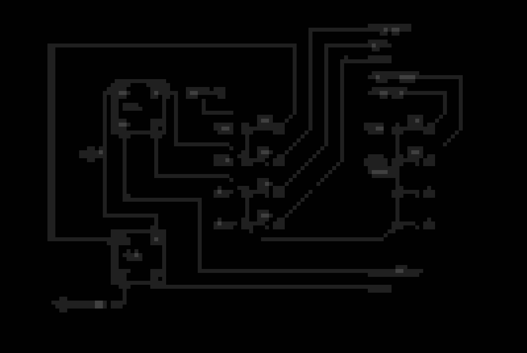
Lets start with the C100/C207 connectors and what's needed for a swap. Omitted wires aren't used EX: 90-92 TBI cars pass VSS wires through the C100

EFI cars are pretty straitforward


Carb cars require a fuseblock be added on. Hard to read, but the jist is the same as 85-87 cars plus a fuseblock


Printer versions


The following 2 users liked this post by Pocket:
Badazz85TA (06-15-2024), mwfrels (07-17-2023)
Old 07-16-2023, 10:15 AM
  #2  
Supreme Member

Thread Starter
iTrader: (24)
 
Pocket's Avatar
 
Join Date: Jun 2005
Location: NC
Posts: 7,931
Likes: 0
Received 142 Likes on 78 Posts
Car: 91 Trans Am
Engine: LSA
Transmission: T56 AWD
Axle/Gears: 8.8 4.10
Re: LS swap wiring diagrams

Fuseblock and AC diagrams. AC can be controlled via PCM or independent. Factory 94-97 LT1 and 98-02 LS1 have the option for PCM control. Other systems should be wired independently. Anything R4, sanden, holley etc should be ran independent


Basic fuselbock


More inclusive fuseblock


The following users liked this post:
mwfrels (07-17-2023)
Old 07-16-2023, 10:19 AM
  #3  
Supreme Member

Thread Starter
iTrader: (24)
 
Pocket's Avatar
 
Join Date: Jun 2005
Location: NC
Posts: 7,931
Likes: 0
Received 142 Likes on 78 Posts
Car: 91 Trans Am
Engine: LSA
Transmission: T56 AWD
Axle/Gears: 8.8 4.10
Re: LS swap wiring diagrams

ECM/PCM diagrams


The following users liked this post:
mwfrels (07-17-2023)
Old 07-16-2023, 10:23 AM
  #4  
Supreme Member

Thread Starter
iTrader: (24)
 
Pocket's Avatar
 
Join Date: Jun 2005
Location: NC
Posts: 7,931
Likes: 0
Received 142 Likes on 78 Posts
Car: 91 Trans Am
Engine: LSA
Transmission: T56 AWD
Axle/Gears: 8.8 4.10
Re: LS swap wiring diagrams

Trans controls and detail of the pedal diagram from the ECM schematics. Compatible pedal PNs and which wires switched between them


Old 07-16-2023, 10:24 AM
  #5  
Supreme Member

Thread Starter
iTrader: (24)
 
Pocket's Avatar
 
Join Date: Jun 2005
Location: NC
Posts: 7,931
Likes: 0
Received 142 Likes on 78 Posts
Car: 91 Trans Am
Engine: LSA
Transmission: T56 AWD
Axle/Gears: 8.8 4.10
Re: LS swap wiring diagrams

6L80E/6L90E


Old 07-16-2023, 10:25 AM
  #6  
Supreme Member

Thread Starter
iTrader: (24)
 
Pocket's Avatar
 
Join Date: Jun 2005
Location: NC
Posts: 7,931
Likes: 0
Received 142 Likes on 78 Posts
Car: 91 Trans Am
Engine: LSA
Transmission: T56 AWD
Axle/Gears: 8.8 4.10
Re: LS swap wiring diagrams

Oddball 98 LS1


Old 07-16-2023, 10:31 AM
  #7  
Supreme Member

Thread Starter
iTrader: (24)
 
Pocket's Avatar
 
Join Date: Jun 2005
Location: NC
Posts: 7,931
Likes: 0
Received 142 Likes on 78 Posts
Car: 91 Trans Am
Engine: LSA
Transmission: T56 AWD
Axle/Gears: 8.8 4.10
Re: LS swap wiring diagrams

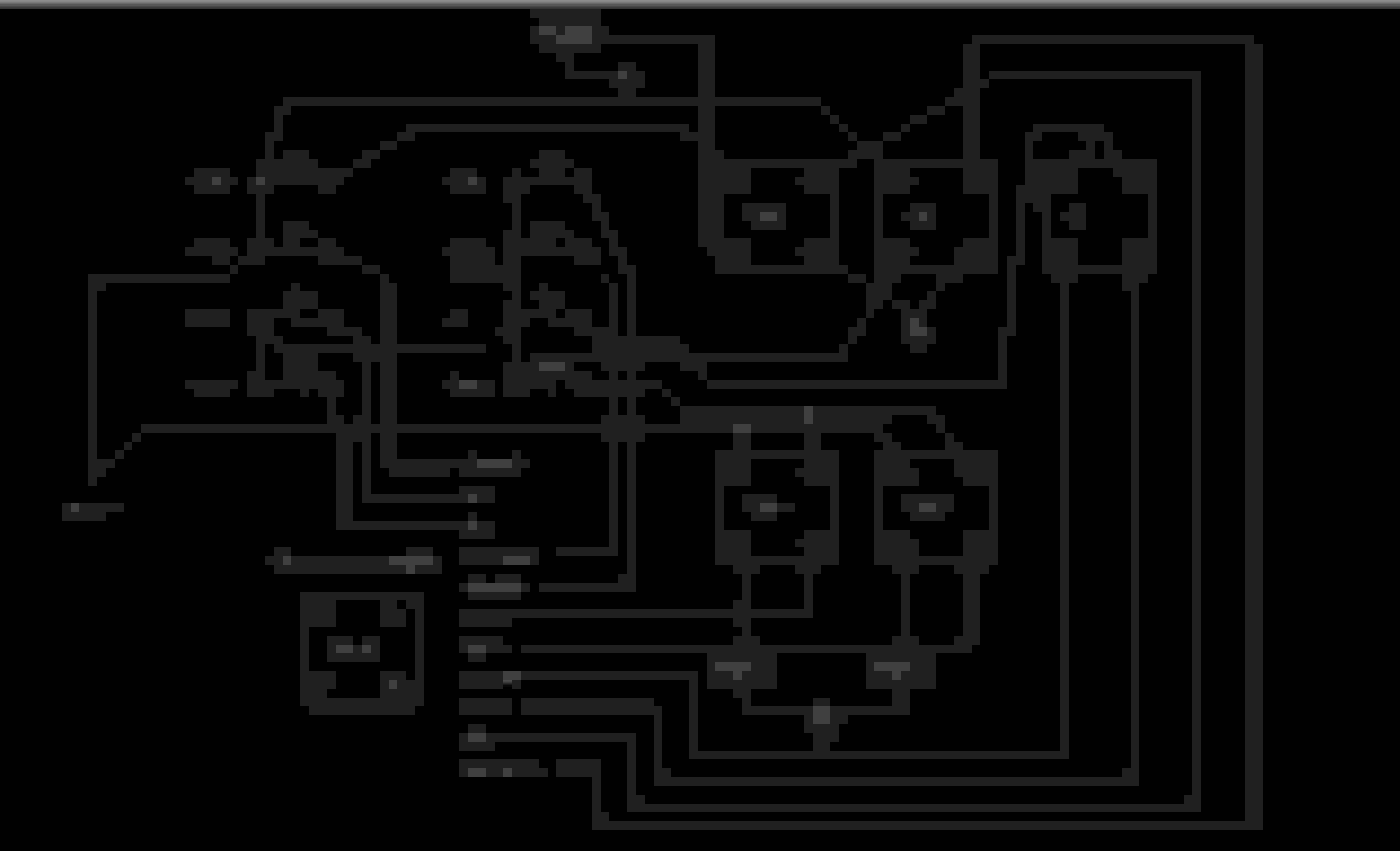
Finally,the holley stuff. These are holley diagrams redrawn for clarity and have the colors changed to the more familiar GM LS. When I grab a random connector, I identify it by wire color/qty. LT GRN, GRY and BLK are MAP for basically anything GM. Holley uses RED/BLK, ORN, BLK/WHT, which is confusing

24x


58x


Trans control
Holley uses a large relay to disconnect the 12v IGN for the trans. If you're building your own harness or adding a fuseblock, then the IGN to the trans REQUIRES A DIODE. Direct 12v IGN will backfeed to the ECU causing a 'no shutdown'. Symptoms: no shutdown, scrambled handheld screen, 6-8v on the circuit key off. In this case, pull the main 40A fuse to the ECU, or unplug the main power connector. Do not leave the ECU powered up like this for long. It does NOT like low voltage situations


09+ 4L60E's have a unique pinout


DBW


Hope these are helpful. God bless

Last edited by Pocket; 07-21-2023 at 07:36 AM.
The following 3 users liked this post by Pocket:
altiller (07-23-2023), punkmaster98 (07-16-2023), WhiteBlaze (08-01-2023)
Old 07-16-2023, 08:14 PM
  #8  
COTM Editor

iTrader: (22)
 
QwkTrip's Avatar
 
Join Date: Mar 2001
Posts: 9,999
Likes: 0
Received 1,912 Likes on 1,305 Posts
Car: '89 Firebird
Engine: 7.0L
Transmission: T56
Re: LS swap wiring diagrams

Thank you!
Old 07-17-2023, 04:03 AM
  #9  
Supreme Member

iTrader: (30)
 
Jaysz28's Avatar
 
Join Date: Jul 2000
Location: Fort Myers, FL
Posts: 1,516
Received 17 Likes on 10 Posts
Car: 91 Firebird
Engine: 6.0
Transmission: T56
Axle/Gears: 3.73
Re: LS swap wiring diagrams

thank you sir!

sticky worthy!
Old 07-17-2023, 07:38 AM
  #10  
COTM Editor

iTrader: (22)
 
QwkTrip's Avatar
 
Join Date: Mar 2001
Posts: 9,999
Likes: 0
Received 1,912 Likes on 1,305 Posts
Car: '89 Firebird
Engine: 7.0L
Transmission: T56
Re: LS swap wiring diagrams

What parts and tools did you use to make the multi-wire splice for common grounds?

I have never been able to find a long crimp splice like GM used.
Old 07-19-2023, 06:12 AM
  #11  
Supreme Member

Thread Starter
iTrader: (24)
 
Pocket's Avatar
 
Join Date: Jun 2005
Location: NC
Posts: 7,931
Likes: 0
Received 142 Likes on 78 Posts
Car: 91 Trans Am
Engine: LSA
Transmission: T56 AWD
Axle/Gears: 8.8 4.10
Re: LS swap wiring diagrams

Originally Posted by QwkTrip
What parts and tools did you use to make the multi-wire splice for common grounds?

I have never been able to find a long crimp splice like GM used.
I solder multi-wire splices. Crimps are fine if done right, but I've replaced a bunch of bad ones. If you plan out solder splice locations or simply loop them, then fracture isn't a concern
The following users liked this post:
Jaysz28 (07-19-2023)
Old 07-20-2023, 01:13 PM
  #12  
COTM Editor

iTrader: (22)
 
QwkTrip's Avatar
 
Join Date: Mar 2001
Posts: 9,999
Likes: 0
Received 1,912 Likes on 1,305 Posts
Car: '89 Firebird
Engine: 7.0L
Transmission: T56
Re: LS swap wiring diagrams

Where did you buy your wire from?

Your schematics already unlocked one the mysteries that was stalling me out on my own project. Easy pleasy now!
Old 07-20-2023, 05:04 PM
  #13  
Supreme Member

Thread Starter
iTrader: (24)
 
Pocket's Avatar
 
Join Date: Jun 2005
Location: NC
Posts: 7,931
Likes: 0
Received 142 Likes on 78 Posts
Car: 91 Trans Am
Engine: LSA
Transmission: T56 AWD
Axle/Gears: 8.8 4.10
Re: LS swap wiring diagrams

Originally Posted by QwkTrip
Where did you buy your wire from?

Your schematics already unlocked one the mysteries that was stalling me out on my own project. Easy pleasy now!
What mystery is that?

I buy my wire from waytek
Old 07-20-2023, 06:29 PM
  #14  
COTM Editor

iTrader: (22)
 
QwkTrip's Avatar
 
Join Date: Mar 2001
Posts: 9,999
Likes: 0
Received 1,912 Likes on 1,305 Posts
Car: '89 Firebird
Engine: 7.0L
Transmission: T56
Re: LS swap wiring diagrams

Originally Posted by Pocket
What mystery is that?
The Holley 4-wire CAN vs. my older harness with 2-wire CAN. Now I see the CAN network is actually still the same, and the extra two wires are power and ground for other hardware.
Old 07-21-2023, 07:30 AM
  #15  
Supreme Member

Thread Starter
iTrader: (24)
 
Pocket's Avatar
 
Join Date: Jun 2005
Location: NC
Posts: 7,931
Likes: 0
Received 142 Likes on 78 Posts
Car: 91 Trans Am
Engine: LSA
Transmission: T56 AWD
Axle/Gears: 8.8 4.10
Re: LS swap wiring diagrams

Originally Posted by QwkTrip
The Holley 4-wire CAN vs. my older harness with 2-wire CAN. Now I see the CAN network is actually still the same, and the extra two wires are power and ground for other hardware.
Yeah, simple IGN/grd. I prefer to use the same IGN source as what goes to the ECU
Strange how holley splices the grd leg into whatever they feel like. LS 24x/58x are in the CRK/CAM circuit, SBC and Coyote all use different pins at the ECU. Holley dominator instructions say to use an external grd. Without knowing the inner workings of the ECU, I just match what their diagrams dictate

Also, I absolutely despise that little CAN connector. For most builds, I tee the two can wires and hard solder them to a laptop cable. The original CAN is present for any accy (handheld, dash, etc) and the laptop cable has far less connection issues. No more ripping your thumbnail off trying to separate them


One last big one I forgot to add to the Holley trans stuff:

The IGN going to the trans connector for 4L60E/80E's REQUIRE A DIODE or it will back feed to the ECU and cause a 'no shutdown' situation. Holley uses a giant Hella relay to accomplish this. If you're building a board, just add a diode
Old 01-31-2024, 01:36 PM
  #16  
Junior Member
 
MacRocZ's Avatar
 
Join Date: Feb 2020
Location: Pensacola, FL
Posts: 17
Received 0 Likes on 0 Posts
Car: 1989 IROCz T-top & 1988 Convertible
Engine: 350 TPI x2
Axle/Gears: 3.73/4.11
Re: LS swap wiring diagrams

This post messed with my mind.

I know I used the same word combo to search if this info was out here! It wasn't then. Looking at the date, this was posted shortly after i completed mine!

Pocket still lives!!!

Heard good things about you pocket! tried to get in touch with you to have you make me a harness. This whole experience grew me into a new love for automotive wiring! Preferably from scratch!
Old 07-09-2024, 07:02 AM
  #17  
Junior Member

 
raybob9289's Avatar
 
Join Date: Oct 2006
Location: Littleton, CO.
Posts: 9
Received 0 Likes on 0 Posts
Car: 1987 Camaro IROC-Z
Engine: LS1
Transmission: T56 6speed
Axle/Gears: 3:45
Re: LS swap wiring diagrams

Pocket,
Thanks for all your schematics. I wired my fans off your schematics fans aren't coming on. I believe the PCM should start 1 fan at about 228°?
I can start the fans manually through my Snap On Solus scanner. But I'm getting the dreaded P0480 & P0481 codes (coolant fan control circuit) ??
PCM is giving my Scanner an accurate temp so it can't be a temp sender?
I put a jumper wire on one of the Relays and physically grounded it to the battery and fan comes on. So my pcm must be bad??
If I posted this in the wrong place my apologies..
Old 07-09-2024, 07:52 AM
  #18  
Supporter/Moderator

iTrader: (7)
 
ShiftyCapone's Avatar
 
Join Date: Feb 2001
Location: Cincinnati, OH
Posts: 13,331
Likes: 0
Received 419 Likes on 320 Posts
Car: '90 RS
Engine: 377 LSX
Transmission: Magnum T56
Re: LS swap wiring diagrams

Originally Posted by raybob9289
Pocket,
Thanks for all your schematics. I wired my fans off your schematics fans aren't coming on. I believe the PCM should start 1 fan at about 228°?
I can start the fans manually through my Snap On Solus scanner. But I'm getting the dreaded P0480 & P0481 codes (coolant fan control circuit) ??
PCM is giving my Scanner an accurate temp so it can't be a temp sender?
I put a jumper wire on one of the Relays and physically grounded it to the battery and fan comes on. So my pcm must be bad??
If I posted this in the wrong place my apologies..
What ECM are you running and do you know if the donor vehicle had PWMF or binary fans? If it had pulse width, the fans will not come on with an ECM signal.
Old 07-09-2024, 09:08 AM
  #19  
Junior Member

 
raybob9289's Avatar
 
Join Date: Oct 2006
Location: Littleton, CO.
Posts: 9
Received 0 Likes on 0 Posts
Car: 1987 Camaro IROC-Z
Engine: LS1
Transmission: T56 6speed
Axle/Gears: 3:45
Re: LS swap wiring diagrams

Originally Posted by ShiftyCapone
What ECM are you running and do you know if the donor vehicle had PWMF or binary fans? If it had pulse width, the fans will not come on with an ECM signal.
I am using the ECM from the donor drivetrain (02 Trans Am) What is PWMF?
Old 07-09-2024, 11:36 AM
  #20  
Supporter/Moderator

iTrader: (7)
 
ShiftyCapone's Avatar
 
Join Date: Feb 2001
Location: Cincinnati, OH
Posts: 13,331
Likes: 0
Received 419 Likes on 320 Posts
Car: '90 RS
Engine: 377 LSX
Transmission: Magnum T56
Re: LS swap wiring diagrams

PWM is pulse width modulation. Its basically a fan that can operate under various speeds. The ECM controls it via a voltage range rather than providing a ground in the traditional sense (just on/off). I don't think the 411 ECM's had PWM on their operating system but I could be wrong.
Old 07-09-2024, 01:15 PM
  #21  
Junior Member

 
raybob9289's Avatar
 
Join Date: Oct 2006
Location: Littleton, CO.
Posts: 9
Received 0 Likes on 0 Posts
Car: 1987 Camaro IROC-Z
Engine: LS1
Transmission: T56 6speed
Axle/Gears: 3:45
Re: LS swap wiring diagrams

Originally Posted by ShiftyCapone
PWM is pulse width modulation. Its basically a fan that can operate under various speeds. The ECM controls it via a voltage range rather than providing a ground in the traditional sense (just on/off). I don't think the 411 ECM's had PWM on their operating system but I could be wrong.
I'm pretty sure my ECM is a 411. Weird how I can activate the fans with my scanner 😆
Old 07-09-2024, 07:29 PM
  #22  
Supporter/Moderator

iTrader: (7)
 
ShiftyCapone's Avatar
 
Join Date: Feb 2001
Location: Cincinnati, OH
Posts: 13,331
Likes: 0
Received 419 Likes on 320 Posts
Car: '90 RS
Engine: 377 LSX
Transmission: Magnum T56
Re: LS swap wiring diagrams

Originally Posted by raybob9289
I'm pretty sure my ECM is a 411. Weird how I can activate the fans with my scanner 😆
Then your ECM is sending a ground signal to the fan relay based on coolant temp reading.
Old 07-10-2024, 10:39 AM
  #23  
Junior Member

 
raybob9289's Avatar
 
Join Date: Oct 2006
Location: Littleton, CO.
Posts: 9
Received 0 Likes on 0 Posts
Car: 1987 Camaro IROC-Z
Engine: LS1
Transmission: T56 6speed
Axle/Gears: 3:45
Re: LS swap wiring diagrams

Originally Posted by ShiftyCapone
Then your ECM is sending a ground signal to the fan relay based on coolant temp reading.
then I don't think so have a bad PCM?? I wonder why I'm getting codes P0480 & P0481??
I guess I might have to get to a tuner sooner than I thought. I was gonna grab another PCM and try it out first. Thanks for your help...
Old 07-11-2024, 10:42 AM
  #24  
Junior Member

 
raybob9289's Avatar
 
Join Date: Oct 2006
Location: Littleton, CO.
Posts: 9
Received 0 Likes on 0 Posts
Car: 1987 Camaro IROC-Z
Engine: LS1
Transmission: T56 6speed
Axle/Gears: 3:45
Re: LS swap wiring diagrams

Delete dreaded trouble codes with my Solus Scanner. Disconnect battery for 15 minutes.
Re-attach positive battery cable and fire up. Let it idle till it gets to 225° and miraculously fan comes on. I love when cars fix themselves.
Ice cold Banquet Beer and the humming of 87 IROC-Z fans. Life is good. 😉
Related Topics
Thread
Thread Starter
Forum
Replies
Last Post
QwkTrip
LTX and LSX
210
01-29-2024 06:18 PM
gt4373
North East Region
0
03-01-2023 11:07 PM
gt4373
North East Region
0
03-01-2022 11:11 PM
FueledSoul
Members Camaros
271
05-30-2021 10:45 PM
black84z28-4spd
Auto Detailing and Appearance
17
10-24-2005 07:07 PM


Quick Reply: LS swap wiring diagrams


All times are GMT -5. The time now is 09:34 AM.