When you click on links to various merchants on this site and make a purchase, this can result in this site earning a commission. Affiliate programs and affiliations include, but are not limited to, the eBay Partner Network.
3D Printed Template for locating Clutch Master Cylinder on firewall
Hello All,
Recently I've finally gotten to my 1982 camaro to swap in a T56 in place of the original automatic TH200. I've been all over the internet gathering ideas and information regarding modifying the firewall to accept the clutch master cylinder. I came up with an approach that I have not seen mentioned anywhere before and thought I would share with everybody, in case this can help.
Using a vernier caliper, I found the two mounting holes for the master cylinder are spaced exactly 78mm apart. I've also determined the angle of the firewall to the cylinder is 45 degrees. I fired up freecad and generated a quick sketch - an 80mm x 80mm plate with two holes spaced diagonally 78mm apart. I then created a datum plane at 45 degrees and put a round hole on that plane, centered between the two holes large enough for the widest part of the cylinder that needs to pass through the firewall. Upon punching this out of the base plate, this created the necessary oval shape needed to cut into the firewall so that the angled master cylinder may pass through, as well as identifies the location for the mounting holes. This eliminates guesswork and minimizes cutting of the firewall. I slid this on the master cylinder to confirm and the holes line up perfectly, while the cylindrical portion of the master cylinder passes right through the oval hole.
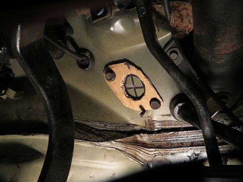
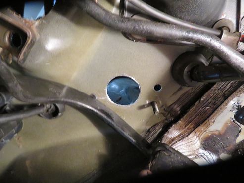
My plan was to locate the two holes via the support braces on the manual pedals (3rd gen one), drill those holes in the firewall and then bolt my 3d printed template in to identify exactly where to cut the oval. However, in my case, it looks like there is already a hole cut out in the firewall with a plug in it which I have punched out. Unfortunately this is not in the correct location and now prevents me from cutting the hole like I wanted to. Nonetheless, I wanted to share this work with the community in case this can help someone else, perhaps some later model cars did not have this hole offset from where I need one for the master cylinder. I'm not sure what option this hole was for, but either way, I will need a new idea for my situation.
I'll attach STL files that you can load directly into your 3d printer software and also freecad source files if you would like to see how it was made and make any changes. This template could also be used to make a sheetmetal "doubler" to bolt down and reinforce the firewall at that location for the master cylinder.
As for my specific situation, I've decided I will use the hole which is already in the firewall and mount the master cylinder in. I will then see exactly where the clutch master cylinder rod lines up with on the clutch pedal and fabricate a bracket which I can then bolt onto the clutch pedal along with a peg that the master cylinder can then interface into, keeping the geometry of that peg and the master cylinder rod in-line and co-planar with eachother. This seems like a better approach as I would rather modify pedals than modify the firewall. As I understand it, the firewall is not as sturdy and rigid as we would like it to be, and taking more material off of it will only weaken it further, so I am not too comfortable enlarging the hole. To those that do not know, it is critical that the master cylinder points straight to the attachment point on the clutch pedal. Any skew on this will produce wear and friction along the sides of the cylinder and eventually cause a leak at the cylinder.
Anyway, I wanted to offer up this approach to the community, as this will probably work for someone out there. If I had a factory manual vehicle, what I would have liked to do was 3D print a bracket that hangs off of the lower two studs of the brake booster and then locates and shows exactly where the master cylinder cutout is along with the two mounting holes. Perhaps someone out there could do so, I think this would be helpful to the community. It looks like the very early thirdgens such as mine will require a different approach. I am hoping a custom bracket to relocate the attaching peg will allow me to use the firewall unmodified.
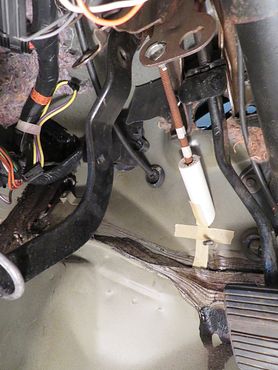
I also generated an alignment tool - a small rectangular piece with two holes spaced 78mm apart and a hole showing true center to them. This was to ensure I had the two support rods on the 3rd gen pedals 78mm apart when up against the firewall, confirming it will align with the master cylinder mount holes (since the rods have adjustment). The center hole would show where center of the oval should be as a sanity check before drilling any holes. This helped me determine that the hole already in the firewall was not where I need it to be. I've attached a picture to illustrate this for those that are curious to see.
Note that this entire approach is theoretical - since I did not get to carry out the install as intended, it is technically an untested method. However, I don't see why it would not work, but as with anything, proceed with care in your project - nothing here is guaranteed to be correct. Ultimately you have to decide if everything looks correct and valid before you proceed with cutting or drilling.
Re: 3D Printed Template for locating Clutch Master Cylinder on firewall
Well FB, we're "sort-a" in the same boat. I believe this is the freshest thread on this topic, that I've found yet. Orangebird, and 69er have been a huge help for me, and OB sent me your thread. My car is an 84, and I have a thread called "firewall pic needed" because of this exact concern. Been trying to research the routes needed to make the automatic/manual swap, and I see quite a few threads on it. lots say they've done it, yet there aren't any good picture postings to show the necessary modifications for the swap. (None that I've found yet, anyway) Just that it's "easy" and "self explanatory". It would be much easier with photos, cause they're worth a thousand words, when peoples terminology differs.
I personally would've preferred a mechanical clutch linkage, but see the cars designers just haven't made it practical. The few "unique" systems out there (82-83 1/2)are made of gold, and no-one will part with them, and the aftermarket doesn't make them. Which leaves us with the option of an expensive redesign of a mechanical system or just install the newer hyd. ones. the latter is supposedly the easiest, but as you've probably found out yourself, if you're doing a conversion from auto to manual, there are quite a few areas that need attention. Which brings me to your cad program template.
Not trying to be disrespectful, but 1st off, just curious why you're quoting mm's? At 1st I thought you were in Britain, or Australia. I know some people are trying to "universalize" the world, but being from the US, I just haven't been familiarized with the metric system as much as everyone else. Of course, we have-ta have metric tools for hardware now-a-days, so that has taken me a step towards the future. No matter, if I were able to understand half of your calculations, maybe I could use your info. If it were me, I would've taken the MC to a piece of cardboard, or matt, and just traced out the pattern. My problem, (as is yours), is how to place it properly on the firewall. Orangebird sent me a nice photo that gives me a "general" idea of where it's located, but as you mentioned above, the push-rod needs-ta be in prefect alignment with the pedal. And I see in schematics the hyd. system pedal has an extension tab heading out, that must be critical to maintaining that geometry. It's too bad the hole in your FW wasn't useable in your case. But I'm sure others, (including me) are thankful for your posting. It would be nice if you could continue this thread with your progress. I'll be doing so with mine. Good luck.
Re: 3D Printed Template for locating Clutch Master Cylinder on firewall
See my posts around #177 in the attached link if you need dimensions and info on location and how to for the clutch master. i have done several of these conversions
Re: 3D Printed Template for locating Clutch Master Cylinder on firewall
Hey Alan, great job on your conversion, and thanks for the link. You used 4th gen pedals, and I see the attachment point where you connect the Heim joint on the MC push rod. I notice it's connected on a stud thru the clutch pedal with no extension, unlike the factory 3rd gen photos I see with a tab extension (off the pedal lever) connecting the push rod. So I assume there's no problem with the geometry? And it appears the 4th and 3rd gen pedals are basically the same ? It still amazes me with the MC push-rod on a 45� angle to the pedal lever, that there's enuff travel to work.
Last edited by tajoe; 07-26-2022 at 07:26 PM.
Reason: mis-spelling
Re: 3D Printed Template for locating Clutch Master Cylinder on firewall
yes the 3rd gen pedal stud is different, you can kind of see it in post 56 of this link on my LS3 swap into my 85 IROC... this was an original 5 speed car and i am using the Tick master to the existing 3rd gen pedal set, i had to adapt to the pin in this case which i describe in post 106 ... if you search you can find pics of this from other users like ghettocruiser i believe
bottom line is you can make this work with either 3rd or 4th gen pedals... personally i prefer the 4th gen pedals and even have changed my 85 iroc to the 4th gen pedal set at this point... i have done many conversions with the 4th gen pedals and this set up i describe
Re: 3D Printed Template for locating Clutch Master Cylinder on firewall
Originally Posted by tajoe
The photo you refer to, (post 56) only shows the push rod "cut off", and not connected to the pedal.
it is actually not cut off, i just dont have the turnbuckle connected and threaded on to it (it is the same master as i used on the other 4th gen pedal swaps in the other threads)... as i said it is giving a relative position to the third gen pedal... i didn't have a pic in that thread as a direct reference. as indicated the written description in post #106 describes what i did but i hadn't taken a picture of the final
Re: 3D Printed Template for locating Clutch Master Cylinder on firewall
Alan, was it your thread, showing the Heim joint connected to the pedal lever, on a stud, that "doesn't" have an extension like the schematic shows? I think we/I just had this conversation, but wasn't sure if it was you. The pic shows it connected directing to the lever, (no extension) on a stud.
Sorry to be redundant with this, but I'm trying not to have-ta re-invent the wheel, if I can find an easy description of how to accomplish this. I know many here have already done this, and know people complain about the same questions being asked. I was told there was a "sticky" on this, yet the sticky itself is very vague when it comes to firewall location, and pedal connection. Just that it's easy. At least you, and some others have posted "some" info, and as mentioned a million times, we really appreciate your picture postings. I can now see in your 88 camaro build, (post 179) the finished connection from 2 views. And you said those are 4th gen pedals.
I guess I too will be re-inventing the wheel on my back, trial and error, trying to mount this MC, and push-rod, but with the help from you guys, I won't be doing it totally blind. Think I'll stop pestering everyone, and dive into it...finally. Maybe I'll be able to add some more photos here, afterwards, and see if they'll aid future members. I'll start a thread on mine too. Thanks again Alan.
Re: 3D Printed Template for locating Clutch Master Cylinder on firewall
it can be hard to search for things in mega threads like some of us post on our builds... as i have been involved in swaps for a long time, i will give you a link to ghettocruiser's thread which i remember from the past that shows another way of thinking about third gen pedals
the other way to do it is the way i did it, which i describe in words in my post #106 in the referenced link, ie i welded on a 3rd gen end from an original master cylinder to the turnbuckle of my tick to mount to the existing pin on the third gen pedal
Re: 3D Printed Template for locating Clutch Master Cylinder on firewall
Wow, what a thread that one is. Know what the most depressing thing about it is, Alan? The car never got finished, after all that "preliminary" work. But I know the feeling, and can definitely relate. I hope he's keeping his head above water.
I see him posting (post 114) about the extension tab I keep referring to, in order to get his MC push-rod connected correctly to the pedal. And I'm not just talking about the stud connection, but the extended tab must be needed to maintain the correct geometry, to make it work. I was just under mine, mickey moused a piece of threaded rod (to simulate the MC push-rod,), placed it in the pedal lever mounting hole for the rod, (which has a black plastic bushing in it), and moved the clutch pedal thru it's travel. With it at a 45� angle, there is no way it's gunna move that MC push-rod enuff, to meet the travel needed to work. I can push the MC push-rod in the MC about an inch and a half, but there's no way the pedal pushes the rod that much, on a 45� angle.
Now, my pedals were bought years ago, and not sure if either of us knew what they came outta. just that they're third gen assys. "Maybe" they happen to be from an 82, with a mech. link, and the hole in the hyd. systems, are located lower? My hole is only approx., and inch under the top pivot point, and the safety sw, is about a couple inches below that. It would seem, if I could drill the safety sw hole out, and mount the pushrod that much lower, I could get the needed travel. (Crazy stuff)
Last edited by tajoe; 07-27-2022 at 06:26 PM.
Reason: other
Re: 3D Printed Template for locating Clutch Master Cylinder on firewall
Some pics to help �. Top is new ready to go on 4th gen pedal. Bottom mc is the actual same tick type I had on my 85 iroc with 3rd gen pedals with the custom rod end I made from cutting off one from a 3rd gen and welding it on
Pedal sets Third gen set is the one I took out of my 85 iroc and as you notice has the tab you mention
yes when adjusted correctly the rod actually moves only about 1 inch �. I have more than enough adjustment range to get all clutches I use to work from Ls to Lt to sbc. It really works many have done this swap
Re: 3D Printed Template for locating Clutch Master Cylinder on firewall
More great stuff Alan. That new 4th gen assy looks premo. Guess I'll have-ta re-fab mine to look like the 3rd gen pic you show. with the tab, and cut out near the bump stop. Mine is fully encased, and if I extend a tab, it'll hit, so I'll have-ta cut out a piece (on the bracket assy.) like on your picture, to clear it.
I'm trying to gauge the distance on the 3rd gen assy, from both the pedals pivot bolt center, to the stud center of the Mc push-rod pin. I told you on mine, the hole centers from the top pivot, to the linkage hole, is only about an inch. Trying to see if yours is farther down or not. getting late here, so I need to check out. Thanks Alan.
Re: 3D Printed Template for locating Clutch Master Cylinder on firewall
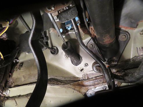
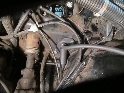
In the middle of it right now. Got the MC mounted..."temporarily", and it was a task that I would've preferred to have all my fingernails, and toe nails, yanked out, individually, than go thru that again. Not that figuring out the location was that difficult, but try being 65, up-side down, under a dash, that has about enuff room to allow 1/2 an African pygmy to maneuver. Could hardly move my second arm under, while trying to hold...anything up. Geesh.
Because all the other advisers didn't really have what I have, (not that I even know what I have), I decided to start at the pedal lever push-rod hole, and work from that point. Knowing the angle that the MC was mounted on the FW, I mickey moused up a threaded rod, and short piece of 1" PVC tubing, to simulate the length of the MC, and push-rod, at it's maximum length.I cut the angle to the PVC, to mimic the MC, and see where it would fit. The threaded rod was long enuff to penetrate into the PVC, but not so long, it wouldn't allow total travel of the pedal, (to the floor.) I began with the pedal pulled all the way against its bump stop, marked the threaded rod with tape at the tube, then pushed the pedal to the floor, and marked it also. then I was able to record the distance the rod traveled. Mounted where it is, it went a full inch, which is the same the MC rod travels from fully extended, to fully compressed.
I'm hoping this will work, cause that's where it's now mounted. Made a cardboard template, and cut the holes where it all lined up.
Next comes figuring out mounting the slave to the next eng. tranny combo. When that's done, then I guess I'll need to go back and stiffen the cheesy firewall.
Last edited by tajoe; 08-04-2022 at 07:21 PM.
Reason: mis-spelling
Re: 3D Printed Template for locating Clutch Master Cylinder on firewall
Hi Guys --
Tajoe the reason for mm is just habit I suppose - the freecad software defaults to mm and so I've gotten used to using it. There is a good picture somewhere of a factory firewall cut out showing the arrangement of holes. I'll include it on this post. Not sure where I grabbed this from, but I'll be clear and say it's not my photo and I do not deserve the credit for it. Using software and providing it with known dimensions of certain things from this photo, it may be possible to compute/generate measurements that could help locate the MC hole and bolt holes. Although since this picture was not taken 100% "straight on", the angle of the picture may distort some of the calculations. In any case, this may have helped you visualize what you were going for as an end result, but it looks like from your pictures you have already made the cut. It looks nice, I'm jealous you had all of that continuous metal to work with!
I haven't gotten back on the master cylinder debacle yet (been working on other things with it) but in the meantime I came up with a possible second idea. I did some google image searching for clutch pedals to brainstorm and found the Ford Focus ST has a clutch pedal with built in master cylinder. I also found the 2010-2015 Camaro clutch pedal design also has the MC built into it, and it's form factor seems very concise, so much that I am considering generating a rectangular, thick bracket to bolt onto the 4 brake master cylinder holes (it would sit behind the pedal assembly bracket) and building a brace behind it on the left side to give it support against the firewall. You can see from the firewall picture that to the immediate left of the raised 4 holes for the pedal assembly is a square cutout for the electrical wires to pass through, but since the brake master cylinder/pedal assembly mount points are raised off the firewall, there will be room behind the bracket for connection to the pedal assembly (high pressure line and clutch fluid reservoir line) - it appears it would just sit above the wire bulkhead. There are adapters out there that convert the quick connect fitting to AN (Russell 640281 I believe), and a custom braided AN line could be made to route to the T56 transmission's slave cylinder. The pedal assembly has two holes on the front side which a bracket could be made to support as well; this appears to me to be just stabilization so the pedal won't have a tendency to shift left or right. The pedal looks to jet out toward the right - if this causes any interference with the brake pedal, this could be bent/cut/welded to sit where it needs to, if everything else worked out right.
I've ordered one of these pedal assemblies from ebay, and once I get a good look at how everything might work, I will report back and let everyone know the plausibility of this approach, whether it looks good or not. This is very out-of-the-box thinking but I'm hoping this will work. With these two unnecessary holes factory cut into the firewall that I cannot use, I am really trying to stay away from cutting more out of the firewall. My research shows one of the holes factory cut and plugged in my 1982 was for a cable driven clutch for the manual transmission option. I believe in 1984 these holes were not included and there is lots more solid metal to work with to create the factory approach firewall-mounted master cylinder mounting hole.
I'll keep you guys posted on any developments or progress. Alan, it looks like you got pretty deep into this too. Perhaps from your experience you know of some gotchyas I may run into with this idea? In the meantime I'll be patiently waiting for my ebay package to find out.

 07-17-2022, 06:28 PM