
What type of Welder
 03-10-2007, 07:21 AM
#51
Supreme Member

iTrader: (1)

Join Date: Jan 2002
Location: garage
Posts: 4,432
Likes: 0
Received 1 Like
on
1 Post
Engine: 3xx ci tubo
Transmission: 4L60E & 4L80E
I guess you could do some sort of foot control using a simple light switch to turn the machine off and on. That would be a little better than constant hot wire at the mig gun. The contactor solution is the best because it disconnect BOTH of the input wires from the wall 115Vac. The stock temperature switch only cuts out one wire of the wall 115Vac.
The weave is a zig-zag side-to-side motion with a slight arc when going from one side to the other. Check out the Hobart welding 101 webpage. It has a picture of the weave pattern.
Last edited by junkcltr; 03-10-2007 at 07:40 AM.
 03-10-2007, 07:58 AM
#53
More difficult than it is worth. It requires a new mig gun and cable that has a gas line in it. A gas valve and control circuit is needed. It would probably cost around $140 - $200 in the end. If I had an HF machine I would not convert it to mig because the cost vs. return is to high. Flux-core can have the same bead as the solid wire. The advantage of the solid is very little smoke (almost none), there is no slag clean up, and less spatter. I would just keep running the HF unit with flux-core. I hate the smoke from the flux-core. Breathing that stuff makes me think that I am going to grow a third nut or something.
Well I guess that a nice machine will go on the shopping list (at the end of course). I also have been looking at mills/lathes, when is this going to end!
He who dies with the most toys...still dies.
03-12-2007, 03:18 PM
#54
Generally, any sort of pattern you move the gun in to fill/create a larger weld bead. In the case of the picture that I posted, I was moving the gun in a sort of reversed C shape, pausing at each end. Another weave that I like is a triangle pattern, roughly forward 2 and up, down, straight back one, repeat� the weld ends up looking exactly like a braid. You can also do stuff like a straight side to side zig zag pausing on the sides (helps to wet in the roots of the weld)�
03-12-2007, 10:56 PM
#55
Supreme Member
iTrader: (1)
Join Date: Jan 2002
Location: garage
Posts: 4,432
Likes: 0
Received 1 Like
on
1 Post
Engine: 3xx ci tubo
Transmission: 4L60E & 4L80E
FWIW, I do quite a bit of fabrication/welding and have my little Hobart hander 135 (workhorse, I�ve fed enough wire through the thing that I�ve worn out parts that don�t wear out, I love that little box), my Miller Synchrowave (think 300# TIG welder, somewhat bigger then the big dorm fridges), and HTP plasma cutter�
big welder cart
big welder cart
Not trying to pick, but your weld cart gives 0 airflow for the HH box. I am guessing that you normally remove it from the cart for any serious welding. I did a dumpster dive for a gas grill frame that I put some plastic containers on for the tips, wire cleaners, nozzles, and extra rolls of wire. It cost about $5 for the containers, $4 for 18 gauge sheetmetal, and $1 for flux-core wire. Just a thought if you decide to put the HH on it's own cart.
03-12-2007, 11:07 PM
#56
Supreme Member
iTrader: (1)
Join Date: Jan 2002
Location: garage
Posts: 4,432
Likes: 0
Received 1 Like
on
1 Post
Engine: 3xx ci tubo
Transmission: 4L60E & 4L80E
Maybe this doesn't apply to anything here, but I took a look at the Miller 135 manual to see if they had the PCB schematic in it. Strange, the HH 140 doesn't have it but the MM135 did. I can see that Miller/Hobart went Hi-tech with the wire tracking compared to what the MM130 had. The PCB is full of OP AMPs and other stuff. It is loaded with stuff like a "real" control ckt would have.
I played around with the flux-core wire quite a bit. One thing that stands out is the weld appearance vs. solid wire. The flux-core gives the stack-dimed look like SMAW would give. MIG is more the smooth solid bead look. In general. the FCAW gives a prettier appearance when compared to MIG with normal welding technique. It seems you can make FCAW look like TIG more easily than MIG.
EDIT: I was also curious as to how the newer HH/MM machines get the 5-10 amps extra out of the box compared to the older units. I think it is the rectifier diodes they are using. With better diodes you get less voltage drop, and along with it less watts chewed up inside the box. That gives more watts to be used in the welding tip.
Last edited by junkcltr; 03-12-2007 at 11:12 PM.
03-14-2007, 01:18 AM
#57
The new, big cart has NOTHING in front or behind the HH, so if anything, it should be better than my old cart that had the bottle mounted right behind the fan, and I�ve never even set that welder thermal breaker off with that one.
Maybe this doesn't apply to anything here, but I took a look at the Miller 135 manual to see if they had the PCB schematic in it. Strange, the HH 140 doesn't have it but the MM135 did. I can see that Miller/Hobart went Hi-tech with the wire tracking compared to what the MM130 had. The PCB is full of OP AMPs and other stuff. It is loaded with stuff like a "real" control ckt would have.
I played around with the flux-core wire quite a bit. One thing that stands out is the weld appearance vs. solid wire. The flux-core gives the stack-dimed look like SMAW would give. MIG is more the smooth solid bead look. In general. the FCAW gives a prettier appearance when compared to MIG with normal welding technique. It seems you can make FCAW look like TIG more easily than MIG.
EDIT: I was also curious as to how the newer HH/MM machines get the 5-10 amps extra out of the box compared to the older units. I think it is the rectifier diodes they are using. With better diodes you get less voltage drop, and along with it less watts chewed up inside the box. That gives more watts to be used in the welding tip.
03-14-2007, 10:03 PM
#58
Supreme Member
iTrader: (1)
Join Date: Jan 2002
Location: garage
Posts: 4,432
Likes: 0
Received 1 Like
on
1 Post
Engine: 3xx ci tubo
Transmission: 4L60E & 4L80E
To be honest, I haven’t done any “serious” welding with it since I put it on the cart, been distracted with other things. That being said, I don’t see how it is going to cause any problems (am I missing something here), the air intake/exhaust/fan are mounted in the front and back of the case, there is nothing, sides, top or bottom.
The new, big cart has NOTHING in front or behind the HH, and I’ve never even set that welder thermal breaker off with that one.
The new, big cart has NOTHING in front or behind the HH, and I’ve never even set that welder thermal breaker off with that one.
Yea, it’s a fairly complicated PCB, I looked into it when I wanted to run mine off of 220VAC just because I had a better 220 outlet then 110 in the garage, but found that it wasn’t a matter of just swapping couple of wires or something simple like most “equipment” is.
_I think_ that I’ve found just the opposite, but I’m not sure that it really matters… I can make either do pretty much what I want it to do when I want it to do it (with the possible limitation of on very thin stuff where then it’s “just be thankful for a clean weld”).
I think it’s mostly advertising and some tweaking of the control circuit. My generation of HH (just before the current 140/180, I think it’s like a 99 or 2000 model), the biggest difference between that 135 and the 180 besides power input was how low the low setting was, the 180 actually had a lower output on the first tap then the 135, similar output on the other taps just shorter duty cycle, it was actually easier to do body metal with the 175, but anything bigger and you couldn’t tell the 2 appart if you were not allowed to see the dial settings (the wire feed is not the same on both). I was under the impression that the 140 was brought more inline with the 175/180 wrt to power, and then got some minor usability and durability tweaks, mostly in the drive assembly
Playing with the welder power electronics got me thinking. I started looking up diodes to see how much power can be saved and used for welding instead of heat in the diodes. Since I need some more practice arc welding, I picked up a used Clarke 131E to practice with. It is a 115v unit so it will probably be more difficult to use than the 220v arc welders that I have used (not many). Since the Clarke 131E is AC only, I bought some used diodes to make it into a DC machine too. I still need to get an output capacitor to smooth out the DC. I want to try it without the capacitor first to see what a difference it makes. I think I will wire it for DCEP only because of the low 115v output. I don't see why I would want to weld anything with it using DCEN and it saves an extra plug/terminal for the ground clamp. I looked into high amp switches but they are too expensive. I even thought about getting another Clarke 131E and putting them in parallel to get a 180 amp machine. It is cheaper to just get the HF 200 AC/DC arc welder. If I really need to arc something big I can use the Airco 225 unit.
EDIT: I don't need an output capacitor for the arc machine. That would try and make it constant voltage (MIG). I need a choke/inductor to make it constant current.
Last edited by junkcltr; 03-19-2007 at 10:47 PM.
03-16-2007, 08:37 PM
#60
Supreme Member
iTrader: (1)
Join Date: Jan 2002
Location: garage
Posts: 4,432
Likes: 0
Received 1 Like
on
1 Post
Engine: 3xx ci tubo
Transmission: 4L60E & 4L80E
I would try TIG with it but every one wants too much money for gas valve tig torch and I can't find a used gas valve that I could control. One like a stock MIG or TIG has. Maybe a nitrous solenoid would work fine.
I have been thinking of trying something with high freq. stabilizer and high freq. start. The thought is to use a stock GM ignition coil and a 4 wire module. I have some old coils and carb computer control ign. modules kicking around. I have a few Atmel AVR chips and FETs too. Maybe even use an old 165 ECM that I have lying around instead.
The thought is to connect the coil output to the AC side of the welder output and charge up the ignition coil for a small amount of time and fire it to generate a spark from the tungsten to the work material for the high freq. start(end goal is aluminum). The thing I haven't figured out yet is how to couple the ignition coil to the welder AC output. The welder will be putting out about 50 Vac open circuit voltage at 60Hz. The coil will put out about 5Kv-40Kv. I need to capacitor couple the two so that the 50Vac doesn't back charge the coil. Maybe some sort of switch instead of the capacitor. A high voltage cap like that is hard to find.
I still need to figure out the high freq. stabilization. Maybe the coil can provide that with a KHz range cycle and lower voltage (1Kv-10Kv). Then their is the need for removing the DC that is created while welding. An inductor that is switched in for TIG use wouldn't be hard to do.
Know any sites that show how they solved the High Freq. start and High Freq. stabilization connection to the AC welder output?
03-17-2007, 02:23 AM
#61
Supreme Member
Join Date: Dec 2005
Location: Texas City, Texas Area
Posts: 1,244
Likes: 0
Received 1 Like
on
1 Post
Car: 89 RS, 92 Z28
Engine: 305 TBI, 350 TPI
Transmission: 700R4 Both Cars
Axle/Gears: 3.23 Posi.. 4 wheel disc both cars
Thought you could stick weld a cage..........Guess I dont know about that .........
03-19-2007, 07:06 PM
#62
Supreme Member
iTrader: (1)
Join Date: Jan 2002
Location: garage
Posts: 4,432
Likes: 0
Received 1 Like
on
1 Post
Engine: 3xx ci tubo
Transmission: 4L60E & 4L80E
The Hobart HH125 MIG conversion pack for $80 seems like a decent setup for doing the TIG gas part of the welder. It comes with a regulator, line, and a gas valve.
The Tesla spark gap circuit seems like the most used for the high freq. start and stabilization. That is what the Lincoln Tig 225 and lots of others use. The ignition coil looks like it would work, but a high voltage cap and homemade transformer are needed. The high voltage design will need some simulations. Some serious harm can be done with it......maybe I am better off with out it.
The Tesla spark gap circuit seems like the most used for the high freq. start and stabilization. That is what the Lincoln Tig 225 and lots of others use. The ignition coil looks like it would work, but a high voltage cap and homemade transformer are needed. The high voltage design will need some simulations. Some serious harm can be done with it......maybe I am better off with out it.
03-19-2007, 07:20 PM
#63
I've been welding on some flanges and stuff this weekend, any tips on how to get those nice welds Crossfire posted? I tried using the "c" weave you talked about as well as the "braid" and it just seems like the finished weld gets bunched up too fast (slowing the wire helped to get it hotter, in turn making them better). They almost looked like a bead of caulking that was never smoothed with a finger. Can get pics if you want.
03-19-2007, 07:59 PM
#64
Supreme Member
iTrader: (1)
Join Date: Jan 2002
Location: garage
Posts: 4,432
Likes: 0
Received 1 Like
on
1 Post
Engine: 3xx ci tubo
Transmission: 4L60E & 4L80E
The weaves we were talking about are used when you V-groove out thick plate and fill the void. I am not sure how thick the plate was that you were welding and how the prep. was done.
83 Crossfire TA's pic is darn impressive. Something that takes practice on junk steel first to get the settings right. For me to get a weld that consistent I need to use two hands and I have a pretty steady hand for soldering small parts. I don't think I have put down a MIG weld as symetric as that ever.....close but not that good. Usually I have to turn up the heat and turn the wire down to get a sizzle-pop weld for small stack beads like that. When I do that I tend to make sure I can always lay down some heat/weld on the back side.
Hopefully 83 Crossfire TA will chime in on how he does it.
Last edited by junkcltr; 03-19-2007 at 08:02 PM.
03-19-2007, 08:18 PM
#65
Yeah, I was wondering if he v-grooved it or not. The welds I was practicing was to get a 2.5" pipe on a 1/4" plate (the nice flange my friend made and didn't want to ruin). I got it welded nice, but it took one full pass, grind, fill hairline cracks, grind, a couple of spots, and grind again. The cheap ferrous SS (1/2" thick and magnetic) that came with my wastegate was actually easier to weld with the MIG than the 1/4" mild steel, lol. I'll go out to the garage and post some pics for you to help me with direction.
Hopefully we are not pirating this thread (like you and I have done in the past, haha) because this still pertains to the origional posters topic.
Hopefully we are not pirating this thread (like you and I have done in the past, haha) because this still pertains to the origional posters topic.
03-19-2007, 09:19 PM
#66
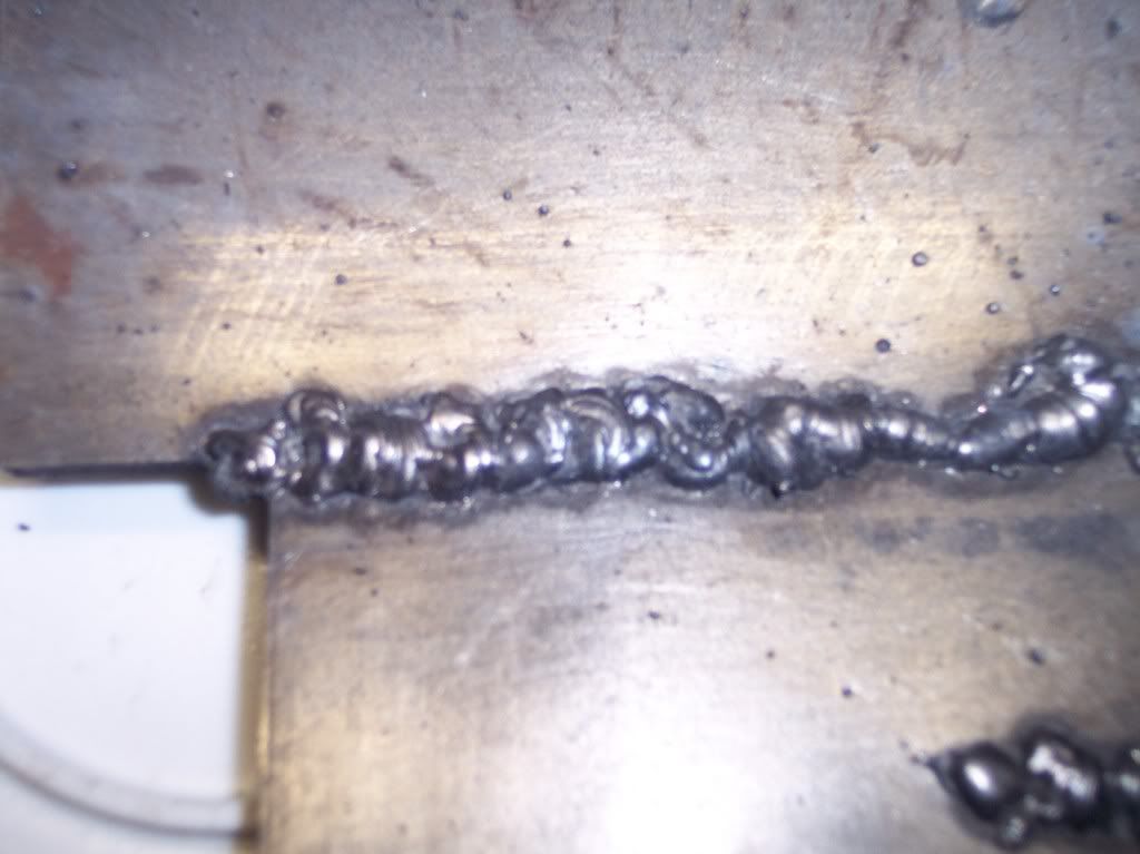
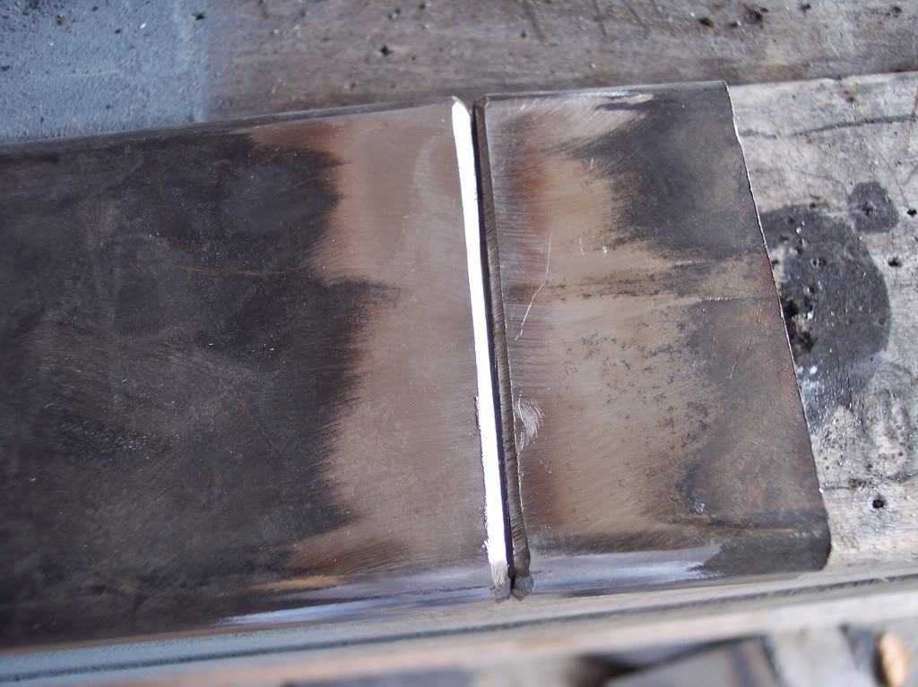
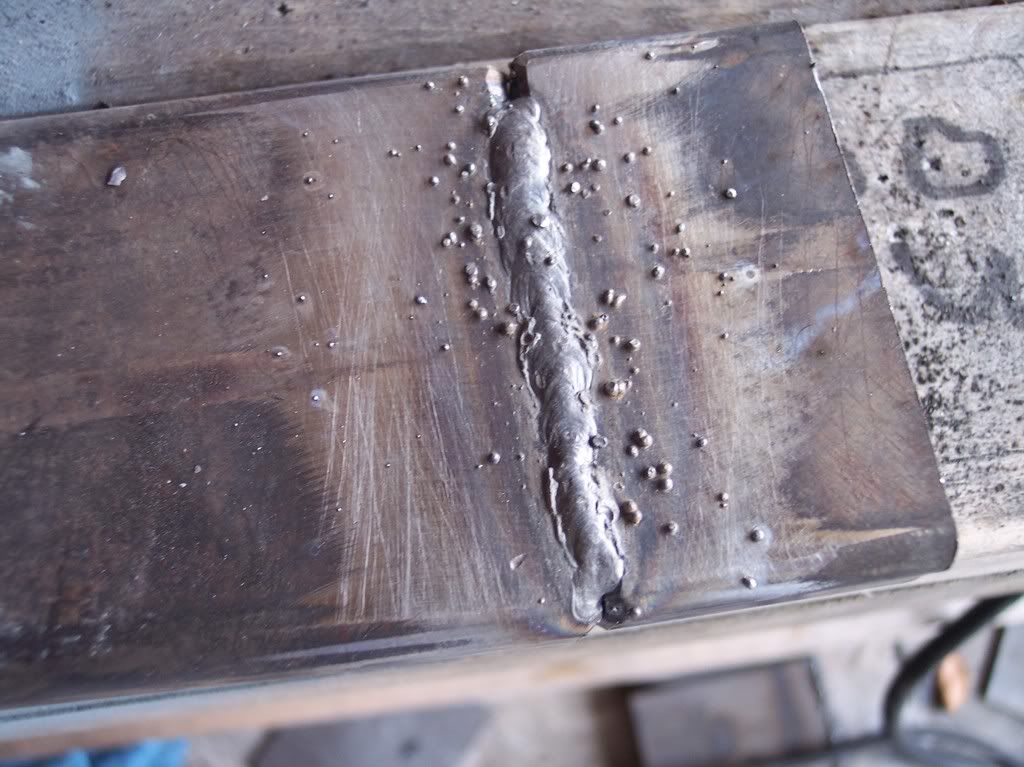
Here's 1/4" mild steel to 1/4" mild steel at about a 15* angle to each other (to create a slight gap).
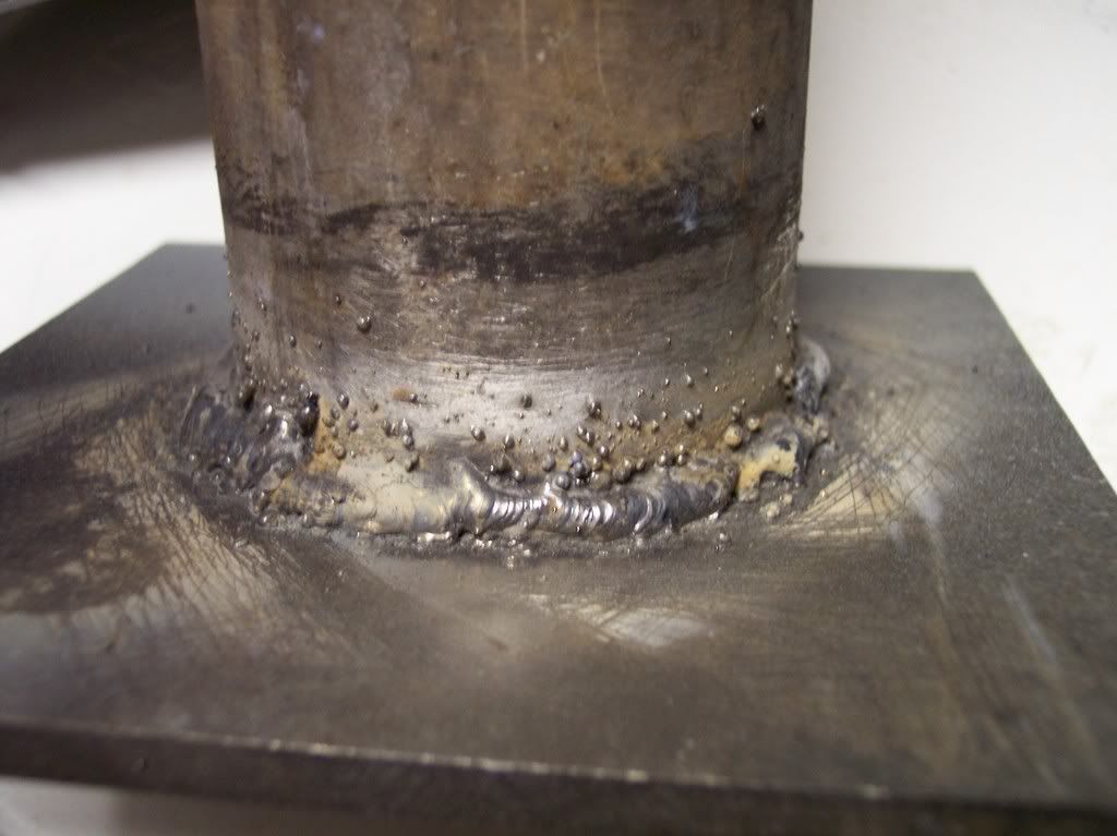
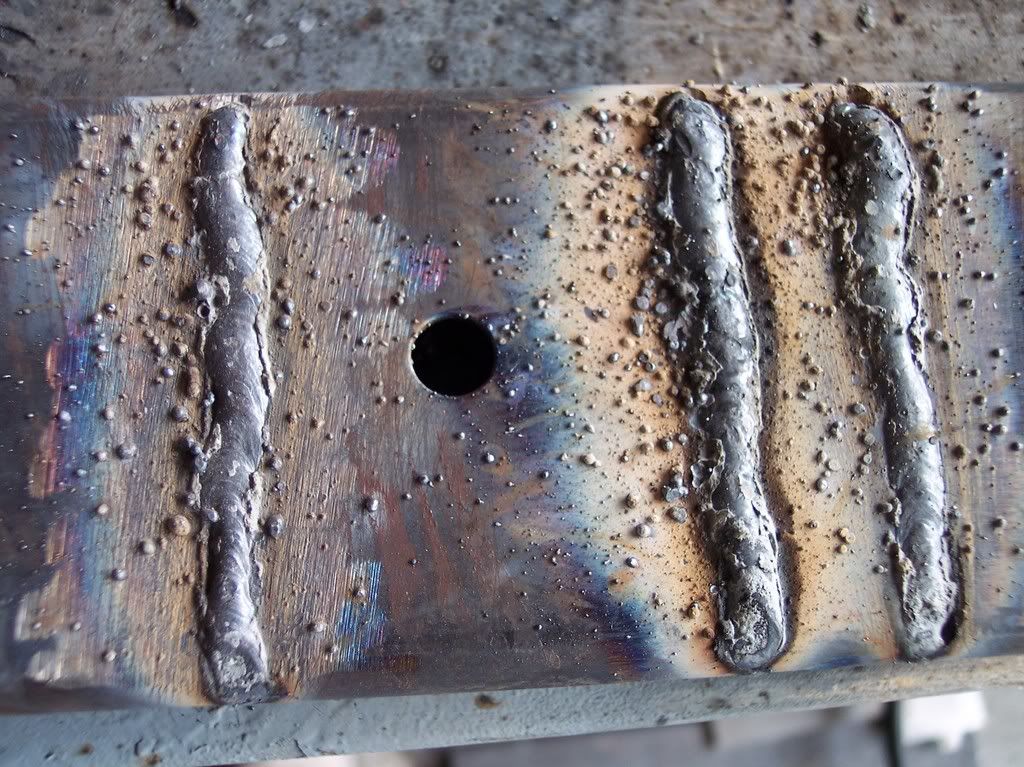
Here is some practice welds on a 2.5" galv. exhaust pipe to a piece of 1/4" mild steel (practice welds/techniques)
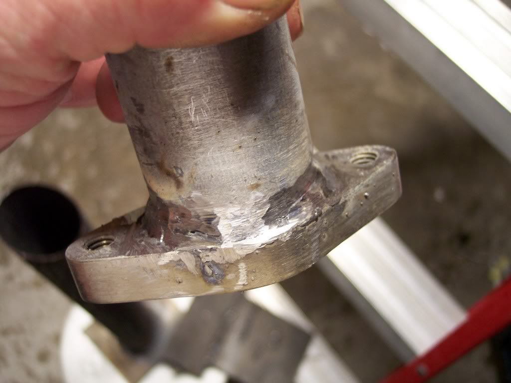
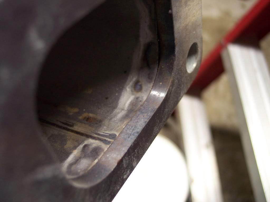
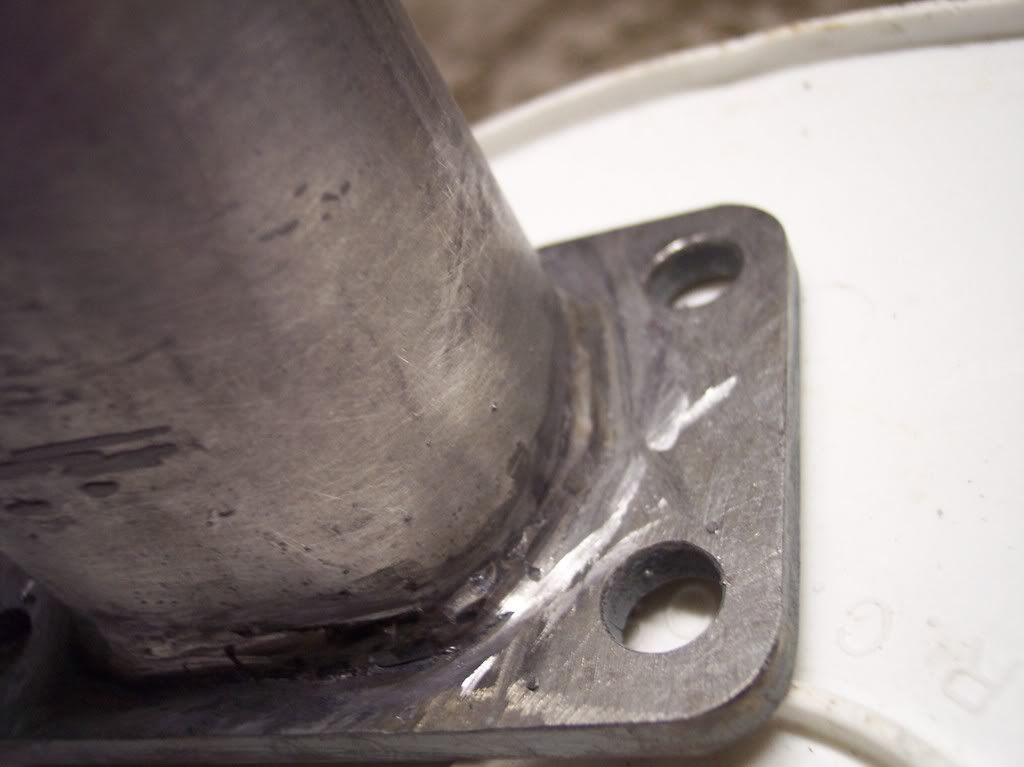
Here is the 1/2" ferrous stainless (counter bored for the pipe) to galv pipe 1/8" thick, couple of more spots to hit before I'm satisfied.
The turbo is tied into position in the car with rope and the flange pipe is bolted to it so I can get you a pic of that later (finished product).
03-19-2007, 10:33 PM
#68
Supreme Member
iTrader: (1)
Join Date: Jan 2002
Location: garage
Posts: 4,432
Likes: 0
Received 1 Like
on
1 Post
Engine: 3xx ci tubo
Transmission: 4L60E & 4L80E
I am a stickler for metal prep so I will start with that. For the 1/4" plate butt weld you need to V-notch the plate. I usually grind at a 45* angle and leave about 1/16" to 1/32" material that will butt against each other. Make sure you surface grind the surrounding metal clean. I usually over grind the surface by about 1/4" where I think I am going to weld. Grind just to get the metal clean/fresh. Only setting back by 1/4" space cuts down on spatter sticking to unwanted areas.
You need more heat. The V-notch will give that using a weave when you do the 1/4" butt weld. For the pipe to plate fillet you need to surface grind both pieces first. It looks like you need to run that machine on the highest voltage output always. Keep the wire stick-out from the tip as short as you can without touching the tip. Less than 1/8" if you are steady enough. Remember the tip is electrically hot and if it is thermally hot during welding and you touch it to the weld you could melt it (destroy it). When welding drag the mig gun towards you (pull the gun towards you). All those will help get better penetration. More wire feed gives more amps up to a point. You will also need to adjust your weld movement speed for the extra wire feed. For the pipe to plate I would do the above with more wire feed and do a weave between the plate and pipe favoring the plate. Do not weld over slag if using flux core. Chip & wire brush if you need to weld over an existing weld. Be picky about because it makes a BIG difference. Cleanliness is very important with MIG/flux-core. What size flux-core are you using? .030" or .035"? I think I would favor .030" judging by the output of the HF MIG machine.
EDIT: That is some nice plate you have their for practice welding. I mainly do dumpster dives for my practice stuff. Ha ha, even for real projects if I can find something that is the correct size. When doing metal prep. my tool of choice is an IR cutoff tool with 3" 1/16" wheels. You can do precise work with it. For the big stuff I use a 4" Makita hand held electric. The die grinder with carbide burrs is used a lot for cleaning up inside pipe welds.
Last edited by junkcltr; 03-19-2007 at 10:51 PM.
03-20-2007, 06:04 AM
#69
The Hobart HH125 MIG conversion pack for $80 seems like a decent setup for doing the TIG gas part of the welder. It comes with a regulator, line, and a gas valve.
The Tesla spark gap circuit seems like the most used for the high freq. start and stabilization. That is what the Lincoln Tig 225 and lots of others use. The ignition coil looks like it would work, but a high voltage cap and homemade transformer are needed. The high voltage design will need some simulations. Some serious harm can be done with it......maybe I am better off with out it.
The Tesla spark gap circuit seems like the most used for the high freq. start and stabilization. That is what the Lincoln Tig 225 and lots of others use. The ignition coil looks like it would work, but a high voltage cap and homemade transformer are needed. The high voltage design will need some simulations. Some serious harm can be done with it......maybe I am better off with out it.

(a split second after this the arc climbed backwards, over the insulator and through the box starting a fire) before I decided that I knew just about enough about electronics to kill myself and not much more. That arc starter circuit was able to jump 3� gaps, ended up using it to power a Jacob�s ladder.
Actually, what really stopped me was that I couldn�t figure out how to protect the welding power supply from the HF/HV power source well/cheaply and then I stumbled on my synchrowave box.
First� threads take on a life of their own, at least the best ones do.
What welder are you using? Wire/wire size/shielding gas?
Not having details, what I can tell for sure is that you�re not running hot enough and/or you�re running too fast. The marbles around the middle weld are caused usually by the wire hitting solid steel rather than being fed into the weld pool. Yes, you will get some of that with flux core and when welding cast pieces (anything with imperfections/dirt), and at the start of some welds, but you shouldn�t be getting that much the whole way around what looks like steel. Get the weld area clean, get some good safety equipment on, and setup someplace where you can get comfortable and get your face in there, right in with the weld so you can see where the wire is going relative to the bead and how putting it in different places in the puddle changes the appearance of the bead (and how it pops and sounds like most monkeys welding when you get out of the weld bead and start hitting solid steel, not that you have that much of a choice on _really_ thin stuff). Once you get comfortable with it you�ll practically be able to do it with your eyes closed, but till then get your face in there, and make sure you can hold your hands still, use 2 hands if you have to, it�s pretty obvious that you�re not steady/jerking around some.
Second, anything thicker then about 1/8� will need some v groove (about 35*) or fit up with a gap with most welders, even TPI383�s MM250 (I really want an MM251�) or you will not get good penetration, and I�m pretty sure that you�ve got somewhat crappy penetration in all 3 of those pics. Unfortunately, I don�t remember what exactly I did for prep in that picture above, but considering how heavy the pieces are and the fact that I remember seeing penetration all the way through I�m pretty sure that I both v-groved it AND left a gap. One thing that I didn�t do that would have helped a little (but left grind marks that I didn�t want) was if I ground back the surface finish on the cast piece some, that would have prevented most of the marbles that you see on mine.
Lastly, check out this attachment� It�s not my weld, but it�s the one that inspired me to play with/tinker with this till I could decide how my weld beads will look, it�s also a pretty good description of the triangular weave that I was talking about that leaves almost like a braid. If I can remember who it was that originally did it I�ll post it, but I do remember it was one of the regulars on the Hobart welding forum, and I�ve had it on my desktop to look at for a long time. If I remember right he said he used an old, 110V miller MIG.
 03-20-2007, 06:36 AM
#70
Junk, that steel is stuff I get free from my buddy at the CNC shop, as it's laying all over the floor in piles to be recycled. It's .030" wire on the HF 90 AMP MIG (as mentioned earlier). I know the prep could be better, but the poping is what I was wondering about. As you guys suggested, I already get my face right down in there and I have leathers. The 1/8" stuff would burn right through if I would go any slower, also how would you prep the counter bored area for the small flange in the pic? I'll try to do some more tonight using your suggestions and see if I can get some more pics.
03-20-2007, 04:59 PM
#71
Supreme Member
iTrader: (33)
Join Date: Jul 2000
Location: Boosted Land
Posts: 5,945
Likes: 0
Received 1 Like
on
1 Post
Car: 92 Z28
Engine: Boosted LSX
Re: What type of Welder
Mark, Id like a new MM251 also.
Ive yet to try this machine with the spool gun and aluminum. I know its deff not gonna be a TIG machine quality etc, but how do you think it will do? (its a PRINCE/COBRA forget which one id have to pull it out nd look again)
Ive yet to try this machine with the spool gun and aluminum. I know its deff not gonna be a TIG machine quality etc, but how do you think it will do? (its a PRINCE/COBRA forget which one id have to pull it out nd look again)
03-20-2007, 11:05 PM
#72
Re: What type of Welder
Here is the only weld I was satisfied with (this was after all the practice, lol) didn't have time tonight for welding, but I did manage to pick up the down pipe flange...
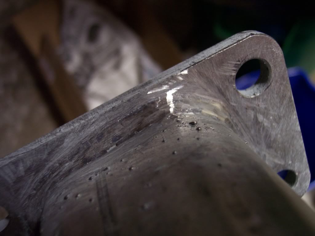
But here is the finished downpipe flange (with the exception of trimming)...
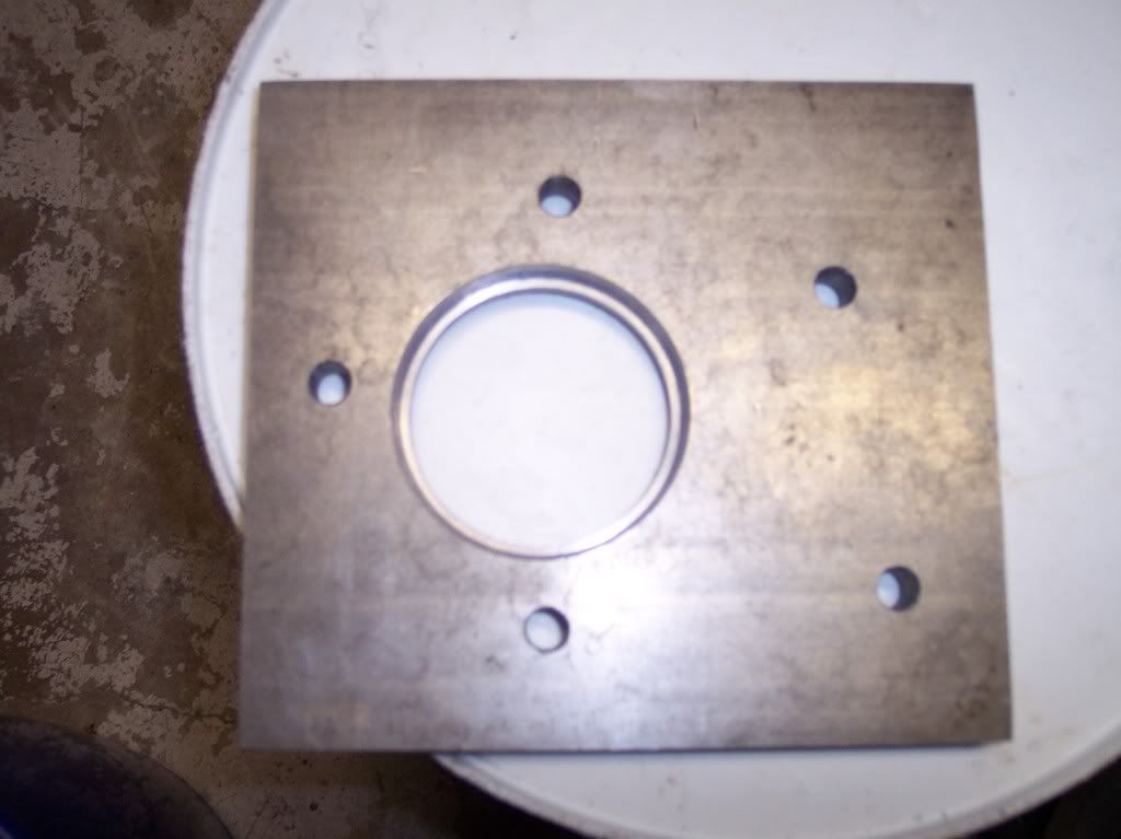
It is 1/2" mild steel that has been counter bored to accept a 2.5" pipe that is 1/8" thick...
But here is the finished downpipe flange (with the exception of trimming)...
It is 1/2" mild steel that has been counter bored to accept a 2.5" pipe that is 1/8" thick...
03-20-2007, 11:46 PM
#73
Supreme Member
iTrader: (1)
Join Date: Jan 2002
Location: garage
Posts: 4,432
Likes: 0
Received 1 Like
on
1 Post
Engine: 3xx ci tubo
Transmission: 4L60E & 4L80E
Re: What type of Welder
Heh, I made it about this far:
PICTURE REMOVED FOR SPACE
(a split second after this the arc climbed backwards, over the insulator and through the box starting a fire) before I decided that I knew just about enough about electronics to kill myself and not much more. That arc starter circuit was able to jump 3” gaps, ended up using it to power a Jacob’s ladder.
Actually, what really stopped me was that I couldn’t figure out how to protect the welding power supply from the HF/HV power source well/cheaply and then I stumbled on my synchrowave box.
The Clarke 131E came in but the 1/16" rod is still on order. I had to try it out so I stuck in the only rod I had lying around which is 7018 1/8". I knew I couldn't do any real welding with it, but I was hoping to get an arc started and watch it pop and spatter at least. That didn't happen. All I could get out of it was a spark or lots of sticking. I then tried a small piece of .030" flux-core. It started to weld and then the entire piece glowed red so I lifted before it exploded/crumbled. I measured the open circuit voltage and it came in at 45 volts. Pulled the cover off to check it out. It is your basic shunt transformer with a capacitor on the main line to help it out a little under load changes. The box is tiny. It is about the size of a little playmate cooler that you would pack lunch in. It looks like a tonka toy. I wish the 1/16" rod would get here.
firstfirebird,
That weld doesn't look bad. Any pics of before you ground it? I might have gone a little wider on the bead on the plate side so I could get more heat/penetration on it.
03-21-2007, 10:59 PM
#75
Supreme Member
iTrader: (1)
Join Date: Jan 2002
Location: garage
Posts: 4,432
Likes: 0
Received 1 Like
on
1 Post
Engine: 3xx ci tubo
Transmission: 4L60E & 4L80E
Re: What type of Welder
Don't be embarassed about it. We all had to learn along the way and with that some things don't come out as well as the stuff done by people with experience. Posting pics on the web is tough because some people want to help and some just want to trash others work. You are fabbing up your own turbo setup. It doesn't get any better than that and you are learning a lot of good stuff along the way......turbo maps, exhaust sizing, welding, machine work, etc. The best part is that if something breaks it is no big deal because you know how to fix it.
03-22-2007, 05:25 PM
#76
Re: What type of Welder
Had time today to weld for a few minutes. Taking your suggestions, I cut this 1"x4" box steel and prepped it:
Then I just cut a bunch of lines in it with a grinding wheel (about 1/4" to 3/16" wide) and put a bead in them experimenting with different angles on the tip:
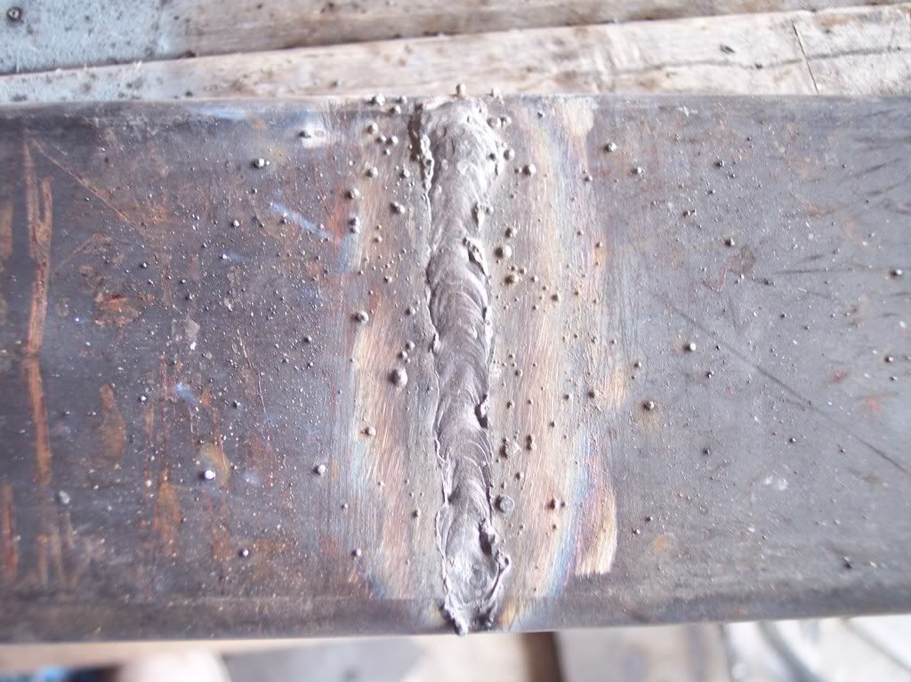
Where in the puddle should the wire be going into? And should I let the wire push the puddle back away from the direction I am welding or keep the wire "pulling" the bead?
Then I just cut a bunch of lines in it with a grinding wheel (about 1/4" to 3/16" wide) and put a bead in them experimenting with different angles on the tip:
Where in the puddle should the wire be going into? And should I let the wire push the puddle back away from the direction I am welding or keep the wire "pulling" the bead?
03-29-2007, 11:11 PM
#77
Supreme Member
iTrader: (1)
Join Date: Jan 2002
Location: garage
Posts: 4,432
Likes: 0
Received 1 Like
on
1 Post
Engine: 3xx ci tubo
Transmission: 4L60E & 4L80E
Re: What type of Welder
Those welds look night and day better than the first ones you posted. They look good. About the only thing I would have done is go a little slower to get more wire in there (taller weld). I feed into the leading edge of the pool as I pull the gun forward. I give it a slight jitter back-forth motion to get the stacked dime / ripple look. The thing about flux-core is that it always looks like you have more wire/filler in the weld than there actually is due to the slag bubbling up.
I finally got around to trying out the Clarke 131E with some 1/16" and 3/32" E6013 rod. It welds 16 gauge with the 1/16" rod very nice and 3/16" plate with the 3/32" good. The only hard part is getting the arc to start, but that is why I bought it anyway. I figured that if I practice with something that is hard to strike an arc with then I will be a lot more comfortable with the bigger machines. The 131E doesn't have a fan so I hit the duty cycle fairly quick. I need to rig up a 115v fan in there somewhere.
I tried out a Clarke 130EN mig unit with flux-core in it. It welds surprisingly smooth. I popped off the cover and noticed that they only have an output choke/inductor. There is no capacitor to keep it constant voltage. They must have put in some design work to get the transformer and choke right. It uses a 4 diode rectifier, contactor, a TINY wire feed motor, and a very simple printed circuit board (PCB). The PCB only has two chips and the rest is resistors and capacitors. Something a DIYer can fix with some help from the web.
04-05-2007, 04:18 AM
#78
Re: What type of Welder
First� those look A LOT better� especially the first and the last pics (the middle ones still don�t look like you got enough heat in them, but better). By where in the puddle are you feeding it� generally, you feed it into the front of the puddle, but if you�re weaving you may end up in the side or the back, just make sure you�re hitting the puddle and not the base metal.
Actually, I�ll say it again� those look a lot better� especially since it looks like that is probably .120� wall or heavier, which is going to soak up a lot of heat so getting a nice, wetted out weld bead like you got in the first or last picture is no small feat with such a small welder.
Actually, I�ll say it again� those look a lot better� especially since it looks like that is probably .120� wall or heavier, which is going to soak up a lot of heat so getting a nice, wetted out weld bead like you got in the first or last picture is no small feat with such a small welder.
04-07-2007, 07:47 PM
#79
Re: What type of Welder
Thanx, Crossfire  . After the suggestions from you and Junk, I am much more confident in my welds holding. That last pic was an accident actually, and was impressed myself. How far should the tip be from the weld (generally speaking)? The last weld I made was where I tapped into the Y-pipe for the inlet side on the turbine of my turbo, and it was really tough to reach. I ended up letting the wire come out quite far and arching to where I needed and seemed to seal up well. If you look in my "Turbo 660 under way" thread (in the power adder forum), you can see where I tapped into the y to wrap the exhaust under the driver's side of the k-mamber, the top of the pipe is what I am talking about (when it's finished, I will take off the y and build a completely new one, but will work for now).
. After the suggestions from you and Junk, I am much more confident in my welds holding. That last pic was an accident actually, and was impressed myself. How far should the tip be from the weld (generally speaking)? The last weld I made was where I tapped into the Y-pipe for the inlet side on the turbine of my turbo, and it was really tough to reach. I ended up letting the wire come out quite far and arching to where I needed and seemed to seal up well. If you look in my "Turbo 660 under way" thread (in the power adder forum), you can see where I tapped into the y to wrap the exhaust under the driver's side of the k-mamber, the top of the pipe is what I am talking about (when it's finished, I will take off the y and build a completely new one, but will work for now).
04-08-2007, 04:27 AM
#80
Re: What type of Welder

I honestly would have guessed that you got the tip closer based on that pic, but if it was further away then go with that. It looks like it might be a little undercut toward the end of the weld bead, which would normally imply too much heat, but I suspect that in your case it�s actually not quite enough filler (speed up the wire feed or slow down your gun travel speed). The fact is that my welds usually get better looking the tighter in I can get till all of a sudden it all goes to hell and I start melting tips and getting big, globby welds, and then going up a wire size and backing the gun off a bit makes them all pretty again, but in some cases things don�t react the way they should, in theory.
For example, what I just said, that undercutting is usually a sign of too much heat� that thickness steel and your little 90A welder I�m sure you�re not getting too much heat and that�s why I gave a different answer. Another situation where that kind of thing happens is if you�re welding �downhill�
The last weld I made was where I tapped into the Y-pipe for the inlet side on the turbine of my turbo, and it was really tough to reach. I ended up letting the wire come out quite far and arching to where I needed and seemed to seal up well. If you look in my "Turbo 660 under way" thread (in the power adder forum), you can see where I tapped into the y to wrap the exhaust under the driver's side of the k-mamber, the top of the pipe is what I am talking about (when it's finished, I will take off the y and build a completely new one, but will work for now).
04-08-2007, 08:21 AM
#81
Re: What type of Welder
That's the abbreviation for 6 cylinders at 60 degrees (popular anoung us 60* guys).
EDIT: Actually to get the jest of the thread, just scroll to the posts with pics as some is just discussion, when it's finished I will mod the first post to be a pictoral of the entire build.
EDIT: Actually to get the jest of the thread, just scroll to the posts with pics as some is just discussion, when it's finished I will mod the first post to be a pictoral of the entire build.
Last edited by firstfirebird; 04-08-2007 at 08:27 AM.
 07-20-2007, 01:33 PM
#83
Junior Member

Join Date: Jun 2007
Posts: 6
Likes: 0
Received 0 Likes
on
0 Posts
Re: What type of Welder
to make a roll cage you want to use a stick welder with 6011-6010 rod the a cover pass with 7018 rod. the idea of useing a mig welder unless your useing a 1500-3000 doller powermig or somting like that is just not really safe or smart, and you can get a nice stick selder for arounf 200-500. tig welders are also good welders but you dont want to skimp when you buy a welder because well lets just say the work will show how well the welder was. flux core IMO is not near as strog and personaly harder to weld with gas is the way to go.
07-20-2007, 01:54 PM
#84
Re: What type of Welder
As for those MIG welds, try and focus on the weld pools edges. It's hard to see, your retina will tend to focus on the white glowing inner part but you need to look at the edges to see if it's wetting properly and not undercutting or laying on there fat. Then you can simply feed into the puddle and move to the leading edge, feed and move...repeat this and you will havea very consistent bead. No need to practise all kinds of weaving techniques (most pople use different techniques anyway, some like triangles, others back and forth, another may like cccc''s or 8888s...)
I didn't read all the above (too much reading LOL), are you using flux core or gas? For clean welding you really need a gas setup. Flux core is only ncie for outside or when you need penetration beyond the capacity of your welder w/ a gas setup.
Last edited by Twin_Turbo; 07-20-2007 at 02:10 PM.
07-20-2007, 02:01 PM
#85
Supreme Member
iTrader: (1)
Join Date: Jul 2004
Location: Calgary, AB, Canada
Posts: 10,763
Likes: 0
Received 4 Likes
on
4 Posts
Car: 1982 Trans-Am
Engine: 355 w/ ported 416s
Transmission: T10, hurst shifter
Axle/Gears: 10 bolt, true-trac, 3.73
Re: What type of Welder
to make a roll cage you want to use a stick welder with 6011-6010 rod the a cover pass with 7018 rod. the idea of useing a mig welder unless your useing a 1500-3000 doller powermig or somting like that is just not really safe or smart, and you can get a nice stick selder for arounf 200-500. tig welders are also good welders but you dont want to skimp when you buy a welder because well lets just say the work will show how well the welder was. flux core IMO is not near as strog and personaly harder to weld with gas is the way to go.
I can't keep an arc stable with AC on a 6010 rod - as it turns out, it's a DC rod.... Duh, no wonder that was such a PITA...
07-26-2007, 04:24 AM
#88
Re: What type of Welder
to make a roll cage you want to use a stick welder with 6011-6010 rod the a cover pass with 7018 rod. the idea of useing a mig welder unless your useing a 1500-3000 doller powermig or somting like that is just not really safe or smart, and you can get a nice stick selder for arounf 200-500. tig welders are also good welders but you dont want to skimp when you buy a welder because well lets just say the work will show how well the welder was. flux core IMO is not near as strog and personaly harder to weld with gas is the way to go.
No matter what you think about welding techniques stick welding isn�t legal for roll cages or for most similar tubular structures (at least until you get to much heavier tube).
As far as strength�. The strength of the weld filler is right in it�s name. NONE of the common fillers used by wire feeders is as weak as your recommended 6011-6010 (which is rated to have a yield of 60Ksi). Most people do roll cages with ER70 or ER80 (70 or 80Ksi) with mig or tig and even the crappiest, basically non rated flux core (E71T-GS, GS stands for General Service and means that it wasn�t certified for any specific use and tends to be about the crappiest wire you can get is still rated for 70Ksi) is stronger then the weld that you�d end up with your recommended stick method (I wouldn�t use a GS wire for a roll cage unless you�re sure that you can do it all in one pass, GS is not rated for multiple pass and generally is a PITA, but I�m fine with flux core in that application)
That's why you can't weld alu properly with DCEN (straight polarity), the straight polarity puts the heat into the work piece and does the actual welding, however the alu oxides melt @ a temp MUCH higher than the aluminium itself, meaning if you welded DC you'd end up w/ a very contaminated weld.
As for those MIG welds, try and focus on the weld pools edges. It's hard to see, your retina will tend to focus on the white glowing inner part but you need to look at the edges to see if it's wetting properly and not undercutting or laying on there fat. Then you can simply feed into the puddle and move to the leading edge, feed and move...repeat this and you will havea very consistent bead. No need to practise all kinds of weaving techniques (most pople use different techniques anyway, some like triangles, others back and forth, another may like cccc''s or 8888s...)
I didn't read all the above (too much reading LOL), are you using flux core or gas? For clean welding you really need a gas setup. Flux core is only ncie for outside or when you need penetration beyond the capacity of your welder w/ a gas setup.
06-30-2008, 01:57 PM
#89
Supreme Member
iTrader: (1)
Join Date: Jan 2002
Location: garage
Posts: 4,432
Likes: 0
Received 1 Like
on
1 Post
Engine: 3xx ci tubo
Transmission: 4L60E & 4L80E
Re: What type of Welder
I also have a HF MIG and the potentiometer is junk. It's inconsistant and by just slightly taping it will cause the speed to change, but like you said once the setting is right it's not a horrible machine (especially for price). I have used it on larger breakers and it still trips the internal breaker that is on a timer for re-start. A way to deal with the crooked wire problem is to fab it up to accept the bigger wire spool which helps keep the wire straighter (and it helped to mess with the tension). I have learned to deal with the wire being hot all the time by resting the chrome end on the piece at an angle so the wire doesn't quite touch, flip the helmet, then lean the wire into the work. In fact I would love to make it work on the trigger and had no idea that was specific to this machine because all of the wire feeds I used were like this. Now you guys have me interested in checking out one of the higher quality units 
I measured the voltage at the gun. On the low setting it was 25vdc and it was 31vdc on the high settings. Since the transformer is only DC rectified then the average is 25/2 and 31/2 or roughly 12vdc and 15vdc. Perfect for an automotive coolant fan / fuel pump relay. I have about 5 old TPI coolant fan / fuel pump relays kicking around. The hand held gun switch switches a small black wire to ground in order to feed the wire feed motor. The weld wire is hot all of the time.
The Modification:
I disconnected the larger "hot" wire that feeds the welding clamp. I then connected a piece of wire from where I disconnected the wire (at the aluminum diode plate) to a coolant fan relay. Then connected the welding clamp wire to the other side of the relay. This is the switch part of the relay. For the relay control coil I connected one side of the coil to the small black wire coming from the hand held gun. The other side of the relay coil was connected to the aluminum diode plate where I added the new wire for the switch part of the relay (this is the 24vdc hot source).
Now the flux core wire is not hot all of the time. It is only hot when the trigger is pressed on the gun. I did about 1 foot of welding to test how hot the relay gets. It seemed "OK" and was a little warm. The machine has a 10% duty cycle so it seems like the relay will out last that. Overall, It took some used wire, a used relay, a few new terminal connectors to make the machine much more usable.........almost for free.
All work was done with the unit disconnected from a power source and all proper safety measures taken.
07-01-2008, 11:37 AM
#90
Supreme Member
iTrader: (1)
Join Date: Jan 2002
Location: garage
Posts: 4,432
Likes: 0
Received 1 Like
on
1 Post
Engine: 3xx ci tubo
Transmission: 4L60E & 4L80E
Re: What type of Welder
I also have a HF MIG and the potentiometer is junk. It's inconsistant and by just slightly taping it will cause the speed to change, but like you said once the setting is right it's not a horrible machine (especially for price). I have used it on larger breakers and it still trips the internal breaker that is on a timer for re-start. A way to deal with the crooked wire problem is to fab it up to accept the bigger wire spool which helps keep the wire straighter (and it helped to mess with the tension). I have learned to deal with the wire being hot all the time by resting the chrome end on the piece at an angle so the wire doesn't quite touch, flip the helmet, then lean the wire into the work. In fact I would love to make it work on the trigger and had no idea that was specific to this machine because all of the wire feeds I used were like this. Now you guys have me interested in checking out one of the higher quality units
Drilled a hole in the front of the machine and installed the 100K pot. Turned on the welder and set the new 100K pot to the middle position. I adjusted the original trimmer to get a medium wire feed speed. The new 100K pot adjusts the wire faster and slower from this nominal speed.
So the free Campbell Hausfeld machine now has $3 into it and works ALMOST like a decent "big 3" 115v machine. Next will be to add a cooling fan to increase the duty cycle. If I come across a terminal block (for changing the polarity to DC+ for MIG) and a gas valve (maybe a used nitrous solenoid) then I would set it up for MIG.
07-04-2008, 01:07 AM
#91
Senior Member
iTrader: (3)
Join Date: Nov 2007
Location: Salt Lake
Posts: 844
Likes: 0
Received 2 Likes
on
2 Posts
Car: 1989 IROC & ROLL-Z
Engine: L98 Vortec FIRST TPI
Transmission: T56, Mech Speedo
Axle/Gears: G92 J65 3.27
Re: What type of Welder
Woah, a written set of instructions for a skill that most definatly should be shown or taught to someone in person.
Anyways, A cheap welder is never worth it. Its not like a tool that you buy that will "wear out" faster than a quality made tool because of its craftsmenship. It will be hard to work with from day one untill the day you throw it away and kick yourself for not speding a few extra bucks for something so versitile for around the house projects of almost any sort.
We have 4 peices of miller equipment at the shop and I love them. Mig, Tig, plasma, and the good old Arc welder. But I have a small lincon Mig at my house, and It has never done me wrong either.
Choose wisley.
07-04-2008, 06:24 AM
#92
Supreme Member
iTrader: (1)
Join Date: Jan 2002
Location: garage
Posts: 4,432
Likes: 0
Received 1 Like
on
1 Post
Engine: 3xx ci tubo
Transmission: 4L60E & 4L80E
Re: What type of Welder
Woah, a written set of instructions for a skill that most definatly should be shown or taught to someone in person.
Anyways, A cheap welder is never worth it. Its not like a tool that you buy that will "wear out" faster than a quality made tool because of its craftsmenship. It will be hard to work with from day one untill the day you throw it away and kick yourself for not speding a few extra bucks for something so versitile for around the house projects of almost any sort.
We have 4 peices of miller equipment at the shop and I love them. Mig, Tig, plasma, and the good old Arc welder. But I have a small lincon Mig at my house, and It has never done me wrong either.
Choose wisley.
Anyways, A cheap welder is never worth it. Its not like a tool that you buy that will "wear out" faster than a quality made tool because of its craftsmenship. It will be hard to work with from day one untill the day you throw it away and kick yourself for not speding a few extra bucks for something so versitile for around the house projects of almost any sort.
We have 4 peices of miller equipment at the shop and I love them. Mig, Tig, plasma, and the good old Arc welder. But I have a small lincon Mig at my house, and It has never done me wrong either.
Choose wisley.
I think in a "hidden box weld" test, most people couldn't tell the difference in a weld between the Miller 115v MIG, Clarke 115v MIG, and the Campbell Hausfeld machine. I would have never thought this until I actually tried it out myself. The Campbell box isn't the greatest thing, but it will do all the projects around a house. It really lays down a nice bead. It surprised me too.
The drive motor in the Campbell Hausfeld machine looks small and may "wear out" faster than the other name brand machines.
07-07-2008, 10:28 AM
#93
Supreme Member
iTrader: (1)
Join Date: Jan 2002
Location: garage
Posts: 4,432
Likes: 0
Received 1 Like
on
1 Post
Engine: 3xx ci tubo
Transmission: 4L60E & 4L80E
Re: What type of Welder
Update:
Some welding was done with the Campbell Hausfeld unit this weekend. There was a failure. The wire would no longer go "hot" after running a few fairly long beads. The problem was that the solder on one of the coolant fan relay joints actually melted off of the pin inside the relay. It welded fine again after putting more solder on the pin. Overall, the coolant fan relay does not seem like a good solution for this machine. A true 12vdc contactor with 20 to 30 amp rated poles will be installed.
Some welding was done with the Campbell Hausfeld unit this weekend. There was a failure. The wire would no longer go "hot" after running a few fairly long beads. The problem was that the solder on one of the coolant fan relay joints actually melted off of the pin inside the relay. It welded fine again after putting more solder on the pin. Overall, the coolant fan relay does not seem like a good solution for this machine. A true 12vdc contactor with 20 to 30 amp rated poles will be installed.
07-07-2008, 10:43 AM
#94
Supreme Member
Join Date: Jul 2005
Location: North Central Mass.
Posts: 2,123
Likes: 0
Received 0 Likes
on
0 Posts
Car: 1985 Berlinetta
Engine: Megasquirted TPI
Transmission: Transgo 700R4
Axle/Gears: 3.42
Re: What type of Welder
I've found that the hobart is one of the best models for your buck.
I ended up with a handler, and it is a great welder.
I ended up with a handler, and it is a great welder.
07-24-2008, 10:25 PM
#95
Supreme Member
iTrader: (1)
Join Date: Jan 2002
Location: garage
Posts: 4,432
Likes: 0
Received 1 Like
on
1 Post
Engine: 3xx ci tubo
Transmission: 4L60E & 4L80E
Re: What type of Welder
You can't go wrong with any of the Hobart machines.
Update:
The 12vdc Gould contactor ($14) from SurplusCenter.com arrived and I installed it. It has 4 poles but only 3 are usable because one is normally closed. The other three are normally open and that is what is needed. Each pole is rated at 20 amps. So it is rated for 60 amps in this setup. I ran a few beads that were long enough to mess up the relay that was in it. The contactor seemed to be cool still. It should last the life of this machine.
Maybe I can post a pic of the setup. It took about 1.5 hrs to install the contactor and make up the wiring. Between the contactor, wire, terminals, and heat shrink it is probably a $20 modification.
07-25-2008, 03:07 PM
#96
Senior Member

Join Date: Feb 2008
Location: Sanford, FL
Posts: 441
Likes: 0
Received 0 Likes
on
0 Posts
Car: 92 RS Camaro
Engine: 305 TBI
Transmission: T5
Axle/Gears: 3.08
Re: What type of Welder
I have a 110v 100amp Flux MiG welder and it is a work horse. I want a bigger one but im able to weld up to 1/2 steel and I can't think of much that I need more of a welder. I know its messy but im not going for show when i am fixing a trailor or fabing up some brackets. I have run my "el cheepo" MiG welder continuously for 3 hours and it gives me no problem and I have had it for a year now. I suggest a flux core mig welder to start because it is easy and cheaper to maintain but if you can get a pretty weld with a flux you can with anything.
07-25-2008, 03:21 PM
#97
Re: What type of Welder
you know, I'm betting a $6-9 ford starter solinoid would make a fine contactor...
As far as not telling what you're welding with... well, unfortunatly your example isn't great, the Clarke machines are decent machines on their own, and the HF, as long as it's in the same class as the rest of the welders should weld similarly (they, like sears/craftsman contract out the manaufacture of tools like that so one of the bigger companies probalby made it anyway).
I'll also dissagree in that you have it backwards. Once you figure out the basics and get a good feel for what you're doing you can pretty much lay down a workable bead with any operational machine. I can actually tell the difference between the Miller, habart and Lincoln small 110/220V welders, but it's because I've used them enough that I know their idiosynchracies and how they react to different situations.
Last edited by 83 Crossfire TA; 07-25-2008 at 03:29 PM.
07-26-2008, 12:34 PM
#98
Supreme Member
iTrader: (1)
Join Date: Jan 2002
Location: garage
Posts: 4,432
Likes: 0
Received 1 Like
on
1 Post
Engine: 3xx ci tubo
Transmission: 4L60E & 4L80E
Re: What type of Welder
As far as not telling what you're welding with... well, unfortunatly your example isn't great, the Clarke machines are decent machines on their own, and the HF, as long as it's in the same class as the rest of the welders should weld similarly (they, like sears/craftsman contract out the manaufacture of tools like that so one of the bigger companies probalby made it anyway).
With the contactor and potentiometer for wire feed speed, this CP machines works quite well for light duty stuff.
07-26-2008, 02:53 PM
#99
Re: What type of Welder
I changed the potentiometer (~$3 for Radio Shack) on my HF machine, and it works exponentially better. I had to cut off the long stem, but the same **** fit right on it. Ever since I bought the machine, the wire speed was erratic and the slightest tough of the **** wold change the speed significantly, not only that, during the welding the wire would change speeds, lol.
07-26-2008, 03:27 PM
#100
Supreme Member
iTrader: (1)
Join Date: Jan 2002
Location: garage
Posts: 4,432
Likes: 0
Received 1 Like
on
1 Post
Engine: 3xx ci tubo
Transmission: 4L60E & 4L80E
Re: What type of Welder
I installed a 100K Radio Shack pot on the Campbell Hausfeld machine because it had a fixed wire speed. What ohm did you use for the pot (100K, 50K, 4K)? The fixed pot. on the PCB was a 420K on this unit.
EDIT: Do you have any pictures of the PCB in the HF machine? Does a black wire come from the mig gun and connect to the PCB? Altogether, are there 4 wires to the PCB?
Wire:
1 black wire from gun to PCB (this wire connects to the welding wire inside the gun when the trigger is pressed)
Since it is flux core the feed wire is the ground side.
2 white wire from diode rectifier (big alum. plate) to PCB
3 red wire from PCB to wire feed motor
4 black wire from PCB to wire feed motor
If so, it is probably like the Cambell machine. The black wire provides a ground to the PCB and runs the motor when the trigger is pressed.
Last edited by junkcltr; 07-26-2008 at 03:33 PM.