
custom v6 intake manifold
 11-29-2006 | 05:58 PM
#1
Thread Starter
Supreme Member
iTrader: (3)
Joined: Dec 2005
Posts: 2,472
Likes: 0
From: Sayreville NJ
custom v6 intake manifold
well i figured id share this
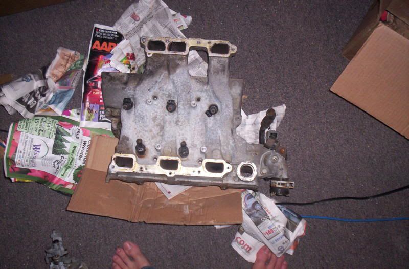
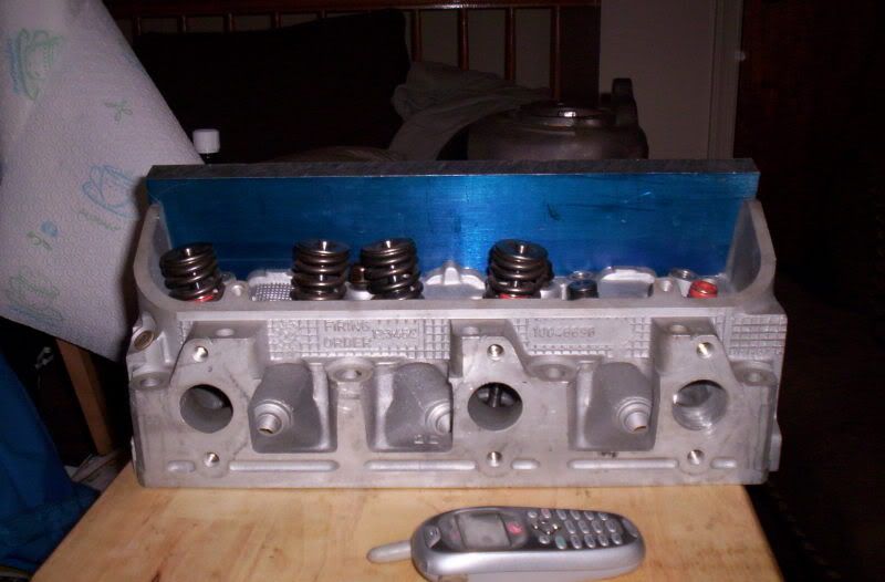
since i swaped to fwd heads on the engine i had to use a fwd manifold.
now the only problem is the fwd manifolds wont clear a distibutor.
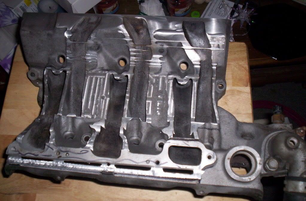
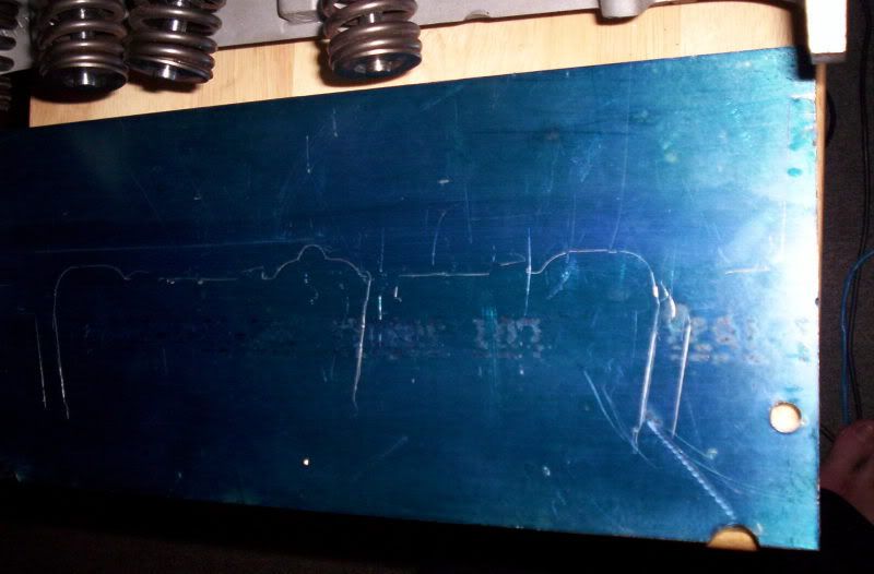
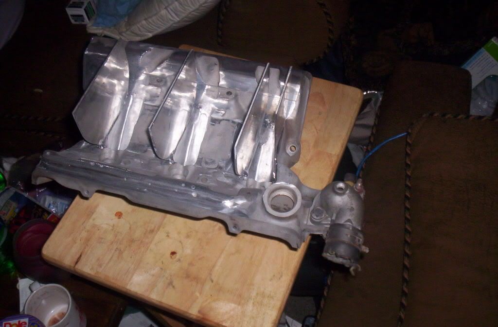
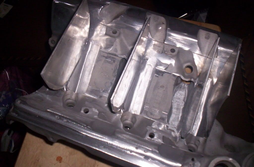
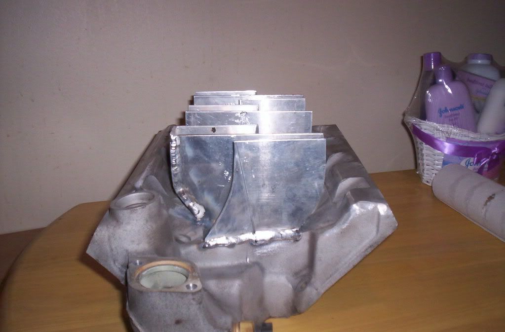
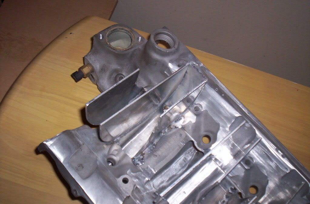
i was able to machine the back of the manifold for dizzy clearance but i didnt stop there,im on my way to machining out the whole middle of the manifold to build a custom sheet metal design.
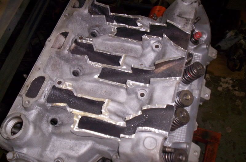
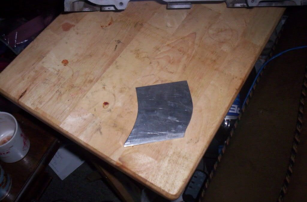
started with this
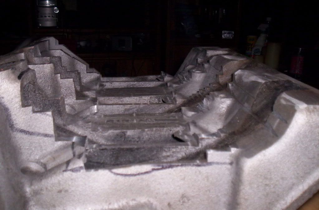
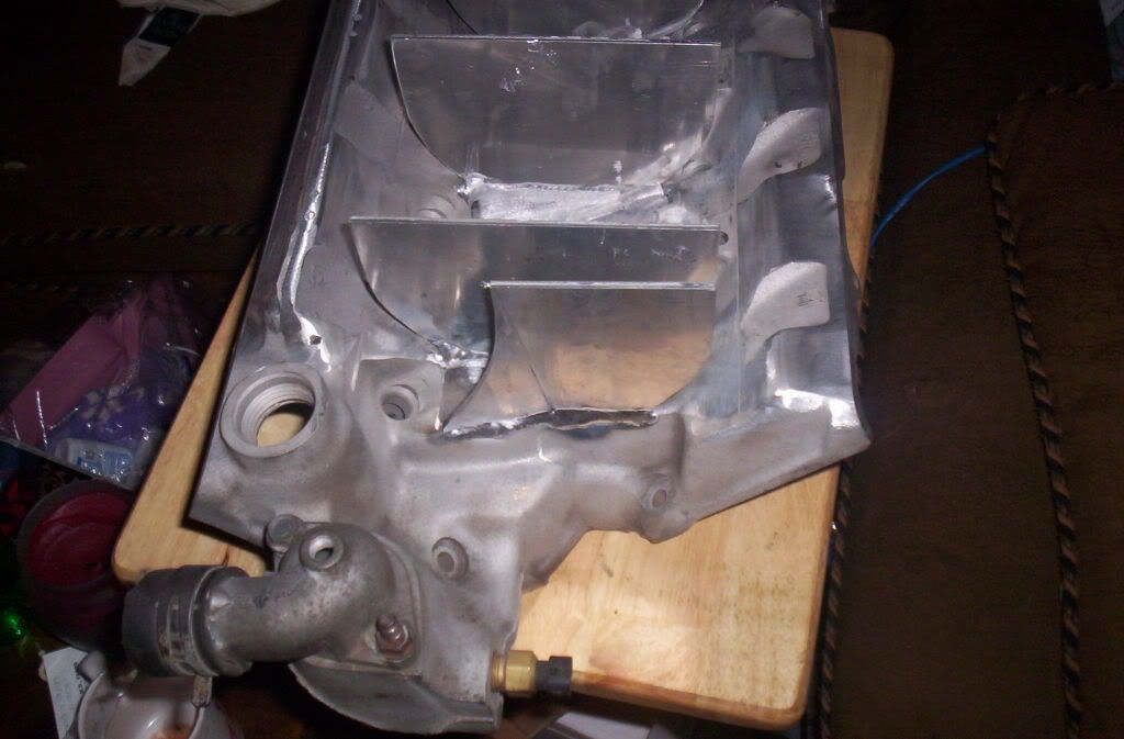
and so far ended up with this
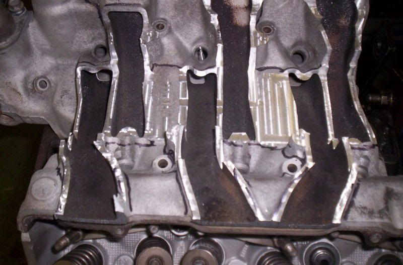
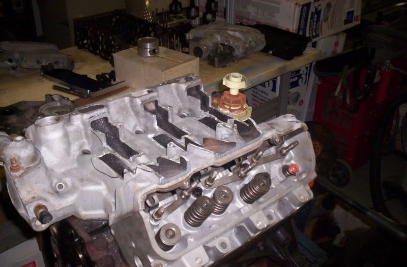
still lots of material to remove before im ready to start fabing runners and such.ill post more pics as progress continues
since i swaped to fwd heads on the engine i had to use a fwd manifold.
now the only problem is the fwd manifolds wont clear a distibutor.
i was able to machine the back of the manifold for dizzy clearance but i didnt stop there,im on my way to machining out the whole middle of the manifold to build a custom sheet metal design.
started with this
and so far ended up with this
still lots of material to remove before im ready to start fabing runners and such.ill post more pics as progress continues
12-15-2006 | 06:55 PM
#2
Thread Starter
Supreme Member
iTrader: (3)
Joined: Dec 2005
Posts: 2,472
Likes: 0
From: Sayreville NJ
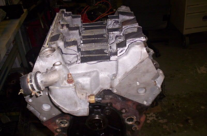
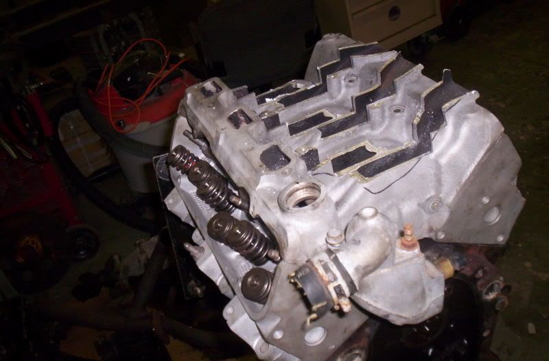
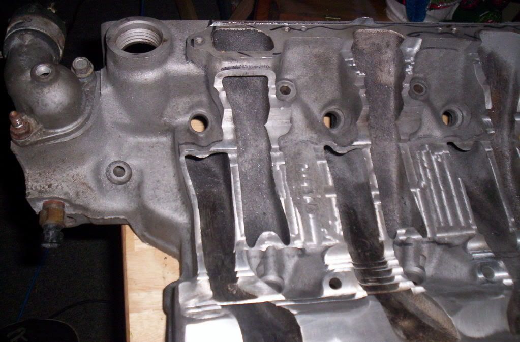
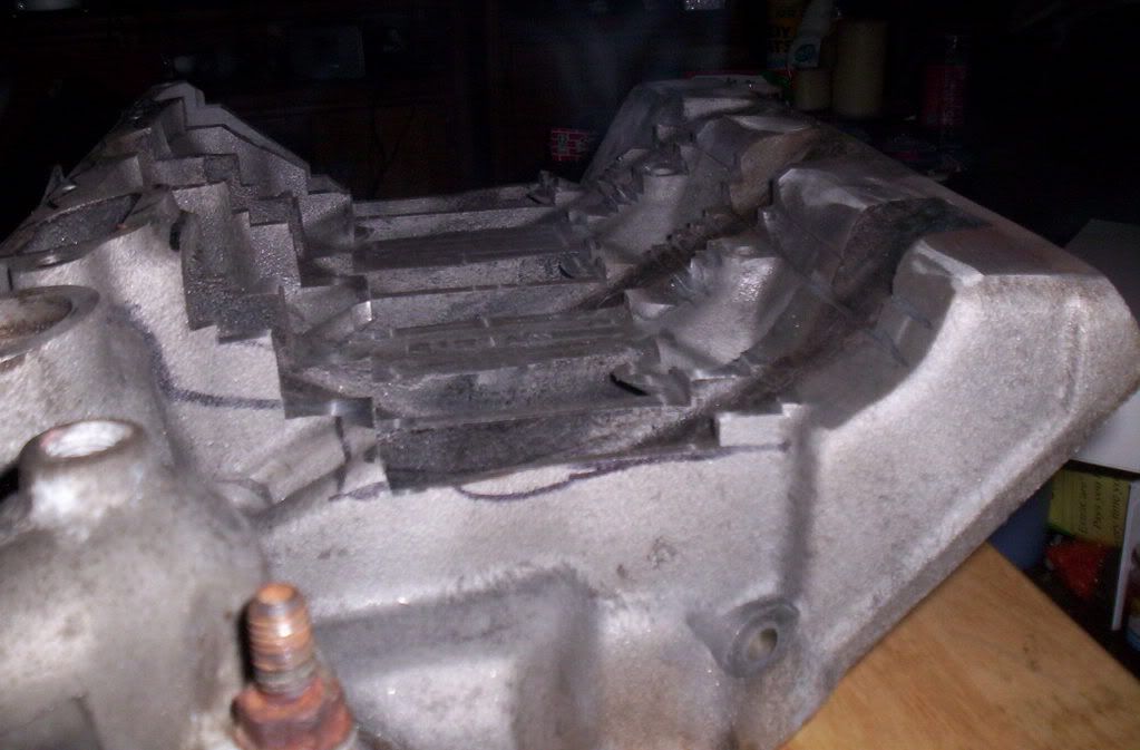
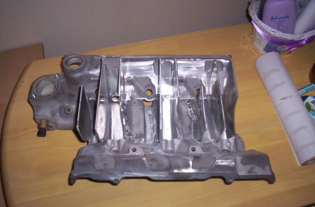
finally had some free tiem to work on this a lil more,ill be finished witht the milling away of the storck runners and the rest of the manifold this weekend.and then i start to build the runners and plenum
Last edited by daves12secV6; 01-04-2007 at 11:45 PM.
12-16-2006 | 05:47 AM
#3

Member
Joined: Apr 2004
Posts: 436
Likes: 0
Car: 1987 TA
Engine: 350 stock/twecked
Transmission: 700r4
Looking good-that seems like it is taking a lot of time to do it the right way-i know this is just an opion, but would it be easier to just fab the complet manifold? Also do those frount weel drive heads flow better, or what benifit do they offer? I am asking as i have a v-6 project to do also
12-18-2006 | 03:12 PM
#4
Thread Starter
Supreme Member
iTrader: (3)
Joined: Dec 2005
Posts: 2,472
Likes: 0
From: Sayreville NJ
no its actually easier to machine a stock manifold down liek i am doing in my case,since i run a turbo charged engine i want a very short runner(about 4 inch long).it is possible to machine an entirely new manifold,but its very hard to do since the port and pushrod layout.the pushrods actually come threw the intake.not to mention the intake is also part of the cyl head/valve cover rail.
the aluminum head are a canted valve design,and flow 60+ cfm better then the iron heads,using the aluminum heads requires u use a fwd pistion,the fwd heads have a 25cc chamber.the iron heads have a 50cc chamber, using rwd pistions with a fwd head will get u a 14.3-1 compression ratio
the aluminum head are a canted valve design,and flow 60+ cfm better then the iron heads,using the aluminum heads requires u use a fwd pistion,the fwd heads have a 25cc chamber.the iron heads have a 50cc chamber, using rwd pistions with a fwd head will get u a 14.3-1 compression ratio
 12-25-2006 | 02:06 PM
#6
Thread Starter
Supreme Member
iTrader: (3)
Joined: Dec 2005
Posts: 2,472
Likes: 0
From: Sayreville NJ
Looking good-that seems like it is taking a lot of time to do it the right way-i know this is just an opion, but would it be easier to just fab the complet manifold? Also do those frount weel drive heads flow better, or what benifit do they offer? I am asking as i have a v-6 project to do also
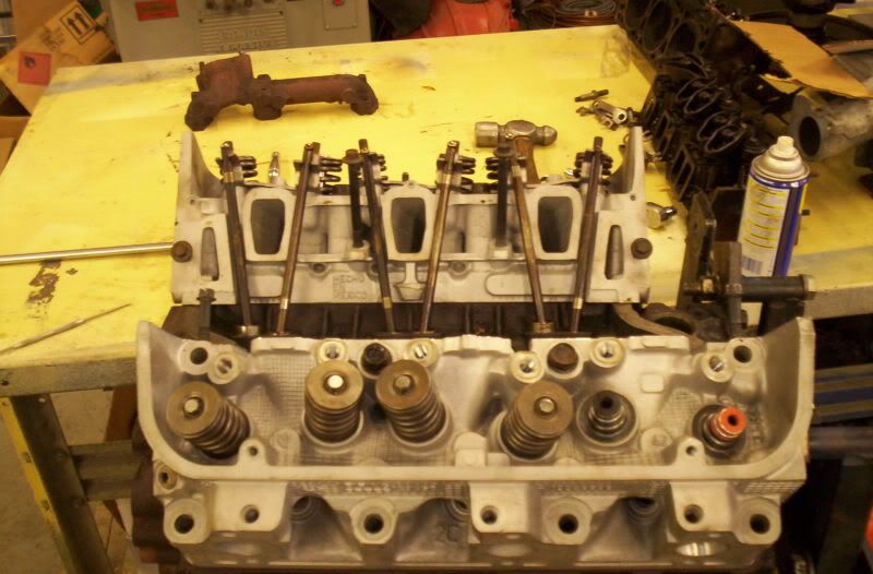
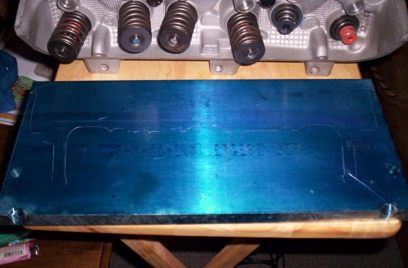
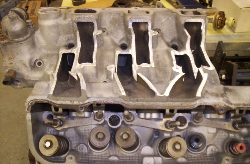
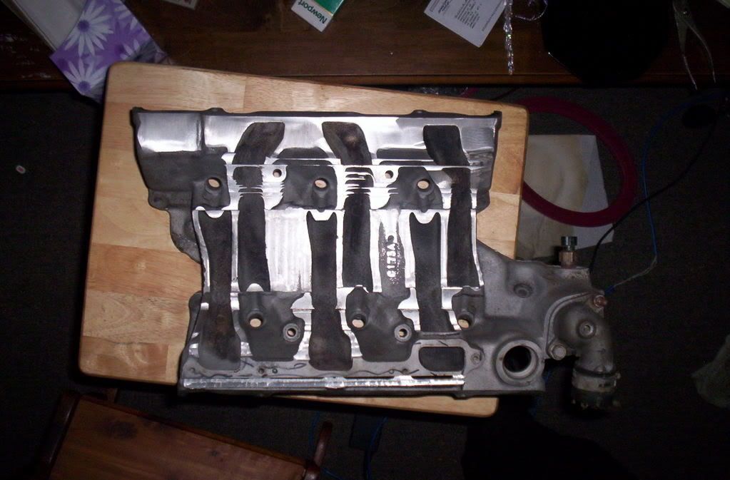
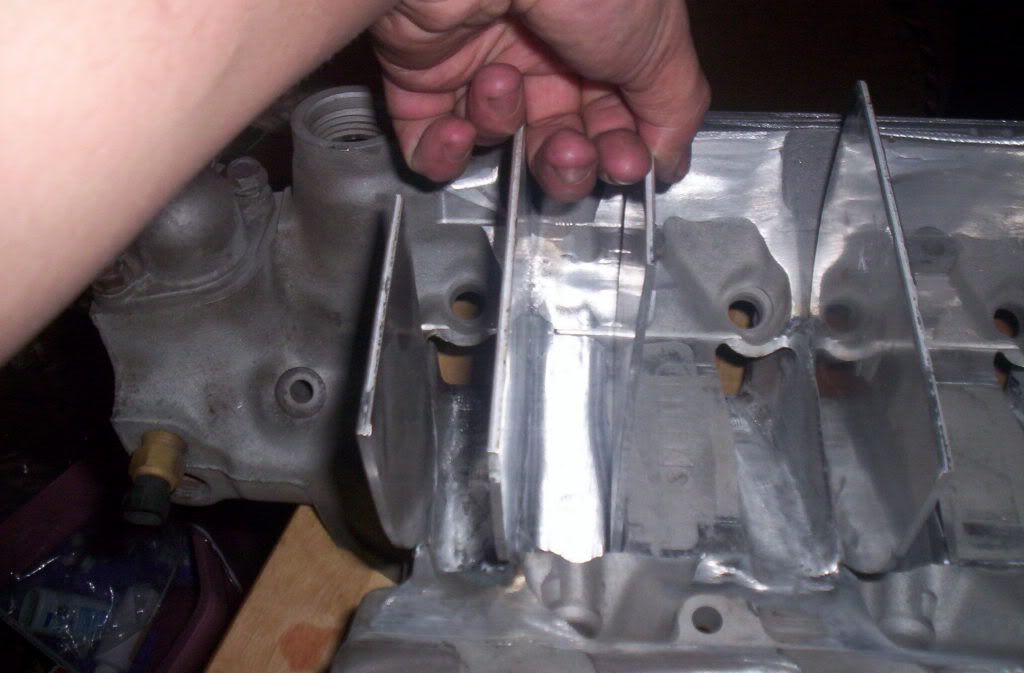
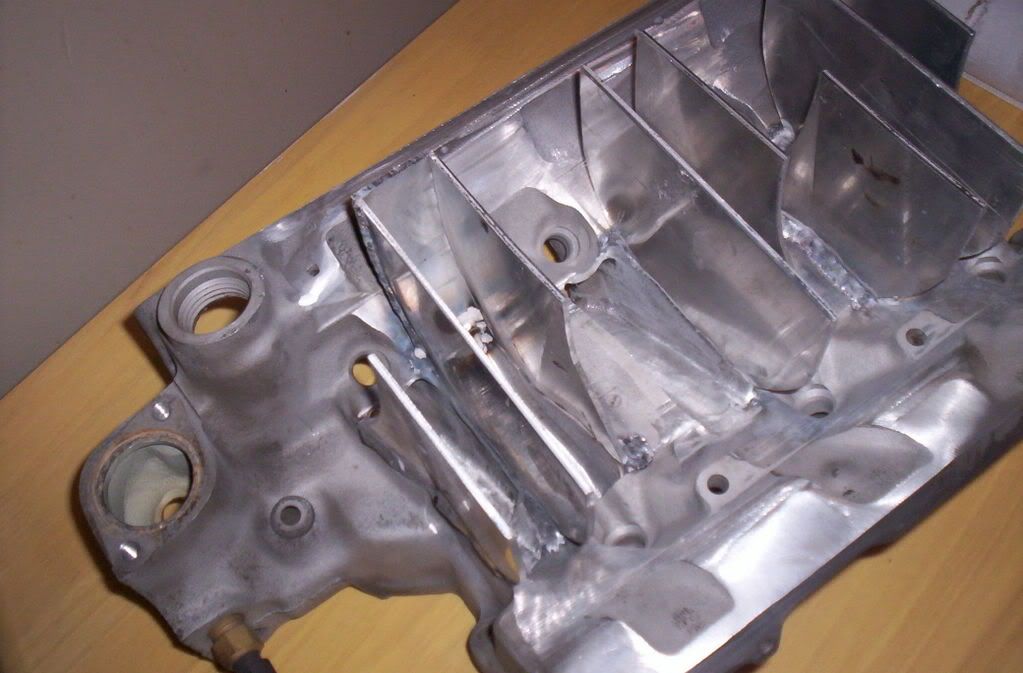
the pushrods would actually come up threw the plates,u can sorta see were i scribed the lines out for them.
also u would have to clearnce out the top portion for the guide plates and rocker arms,i found a simpler way of doing it but stoped working on the plates once i started to machine away the stock manifold to use.
next time i goto work ill dig out the plates that i machined for the pushrods and guideplates/rockers and take some pics with them installed.
besides all of the above when welding it all together there would be some issues with it warping and possibly not sealing up correctly,which is greatly reduced using the stock manifold base and machining it the way i am doing
Last edited by daves12secV6; 12-25-2006 at 02:09 PM.
12-25-2006 | 07:02 PM
#7
Supreme Member
iTrader: (3)
Joined: Feb 2006
Posts: 1,093
Likes: 0
From: western ny
Car: '82 formula clone, 95 saab 900se
Engine: 350 vortec'd tbi, 2.0L turbo
Transmission: 700r4, 5 spd
Axle/Gears: 10 bolt 2.77 open
looks like a nifty new idea, i'm pretty interested. keep us updated on the progress.
Trending Topics
12-30-2006 | 03:28 PM
#8

Joined: Jun 2001
Posts: 7,980
Likes: 85
From: DC Metro Area
Car: 87TA 87Form 71Mach1 93FleetWB 04Cum
What kind of a mill/equipment do you have access to? Not a bad job… looks like some of the stuff that I’ve done with a router and a lot of perseverance….
12-30-2006 | 04:33 PM
#9
Supreme Member
iTrader: (17)
Joined: Jan 2005
Posts: 2,716
Likes: 2
From: Mobile, AL
Car: GTA
Engine: 383 HSR
Transmission: TH-700R4
Axle/Gears: 3.42
----------
I am a huge "no replacement for displacement" kind of guy however, I like your attitude towards the V6's. If you intend to use the aluminum heads and RWD pistons and you have a compression ratio of 14.3:1 Then on your turbo charged application it seems you will not be able to increase your PSI by very much. I would guess no more than 5? Unless of course you ran some race gas of some sort.
So what is your plan to tackle your high compression turbo charged motor?
My guess would be to give your heads a bowl job and raise the cc's some more so you can run some more PSI on those bad boys. or get some Dead soft copper sheets that are pretty thick and trace and cut your own head gaskets. Or a combo of the two. I would not trust just any head gasket on this project.
I am guessing you want to use the RWD pistons... what comp ratio you working with with those?
I am interested in what you have going on.
no its actually easier to machine a stock manifold down liek i am doing in my case,since i run a turbo charged engine i want a very short runner(about 4 inch long).it is possible to machine an entirely new manifold,but its very hard to do since the port and pushrod layout.the pushrods actually come threw the intake.not to mention the intake is also part of the cyl head/valve cover rail.
the aluminum head are a canted valve design,and flow 60+ cfm better then the iron heads,using the aluminum heads requires u use a fwd pistion,the fwd heads have a 25cc chamber.the iron heads have a 50cc chamber, using rwd pistions with a fwd head will get u a 14.3-1 compression ratio
the aluminum head are a canted valve design,and flow 60+ cfm better then the iron heads,using the aluminum heads requires u use a fwd pistion,the fwd heads have a 25cc chamber.the iron heads have a 50cc chamber, using rwd pistions with a fwd head will get u a 14.3-1 compression ratio
So what is your plan to tackle your high compression turbo charged motor?
My guess would be to give your heads a bowl job and raise the cc's some more so you can run some more PSI on those bad boys. or get some Dead soft copper sheets that are pretty thick and trace and cut your own head gaskets. Or a combo of the two. I would not trust just any head gasket on this project.
I am guessing you want to use the RWD pistons... what comp ratio you working with with those?
I am interested in what you have going on.
Last edited by nelapse; 12-30-2006 at 04:36 PM.
12-30-2006 | 07:13 PM
#10
Thread Starter
Supreme Member
iTrader: (3)
Joined: Dec 2005
Posts: 2,472
Likes: 0
From: Sayreville NJ
----------
I am a huge "no replacement for displacement" kind of guy however, I like your attitude towards the V6's. If you intend to use the aluminum heads and RWD pistons and you have a compression ratio of 14.3:1 Then on your turbo charged application it seems you will not be able to increase your PSI by very much. I would guess no more than 5? Unless of course you ran some race gas of some sort.
So what is your plan to tackle your high compression turbo charged motor?
My guess would be to give your heads a bowl job and raise the cc's some more so you can run some more PSI on those bad boys. or get some Dead soft copper sheets that are pretty thick and trace and cut your own head gaskets. Or a combo of the two. I would not trust just any head gasket on this project.
I am guessing you want to use the RWD pistons... what comp ratio you working with with those?
I am interested in what you have going on.
01-01-2007 | 02:44 PM
#12
Thread Starter
Supreme Member
iTrader: (3)
Joined: Dec 2005
Posts: 2,472
Likes: 0
From: Sayreville NJ
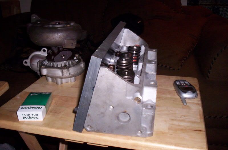
im unsure right now,only cause i dont know how much power it will make per said boost level,this new motor should make the same numbers my other motor does at a lower boost level.but just do give u an idea i ran 18+psi on my old motor,though i saw lil gain over 18 psi,due to the turbo pretty much being maxed out at 18 psi so efficancy droped pretty fast above that.
this motor is getting twin T04E's instead of the single T04E i used to run.
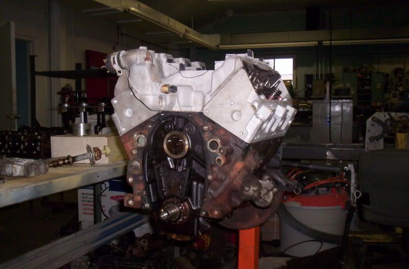
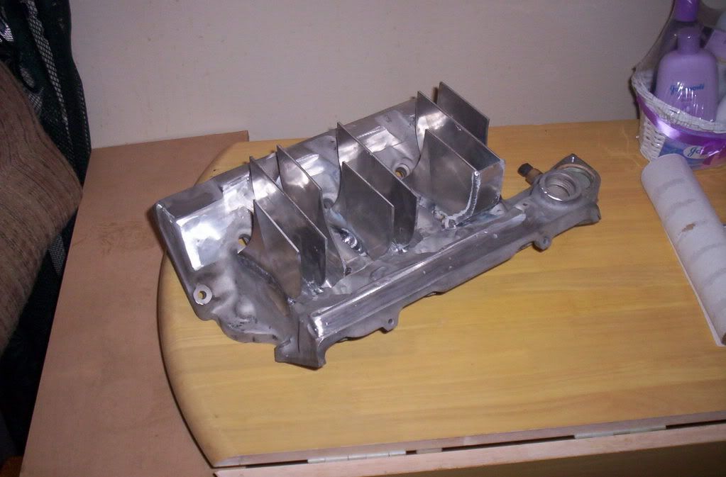
btw ill have more pics tonight,i finished maching the manifold and have started to fab/weld on the new runners,so ill bring the manifold home with me and take some pics and post them up
this motor is getting twin T04E's instead of the single T04E i used to run.
btw ill have more pics tonight,i finished maching the manifold and have started to fab/weld on the new runners,so ill bring the manifold home with me and take some pics and post them up
01-01-2007 | 04:11 PM
#13
Supreme Member
iTrader: (17)
Joined: Jan 2005
Posts: 2,716
Likes: 2
From: Mobile, AL
Car: GTA
Engine: 383 HSR
Transmission: TH-700R4
Axle/Gears: 3.42
twin turbo would be a much more efficient way to go. The beauty of twin turbos is that you can reduce turbo lag greatly by having two different size turbos that spool different at certain rpms. Thus, creating constant and quick boost when your engine demands it. If you have the dollar, some single snail turbos are more efficient than any twin setup, but the price is a bit out rageous.
 01-01-2007 | 08:29 PM
#16
Senior Member
Joined: Sep 2006
Posts: 747
Likes: 1
From: Reno, NV
Car: 1982 Z28 & 1967 RR/SS 396
Engine: ZZ383 & 375hp 396
Transmission: T56 & factory TH400
Axle/Gears: 9" ford & 12 bolt 4.10
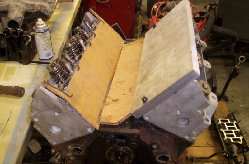
Looks very good so far.
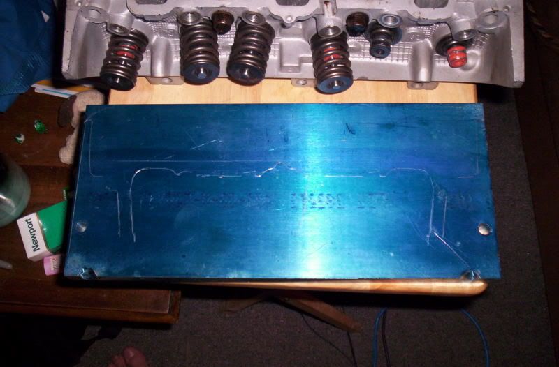
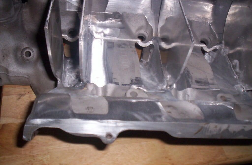
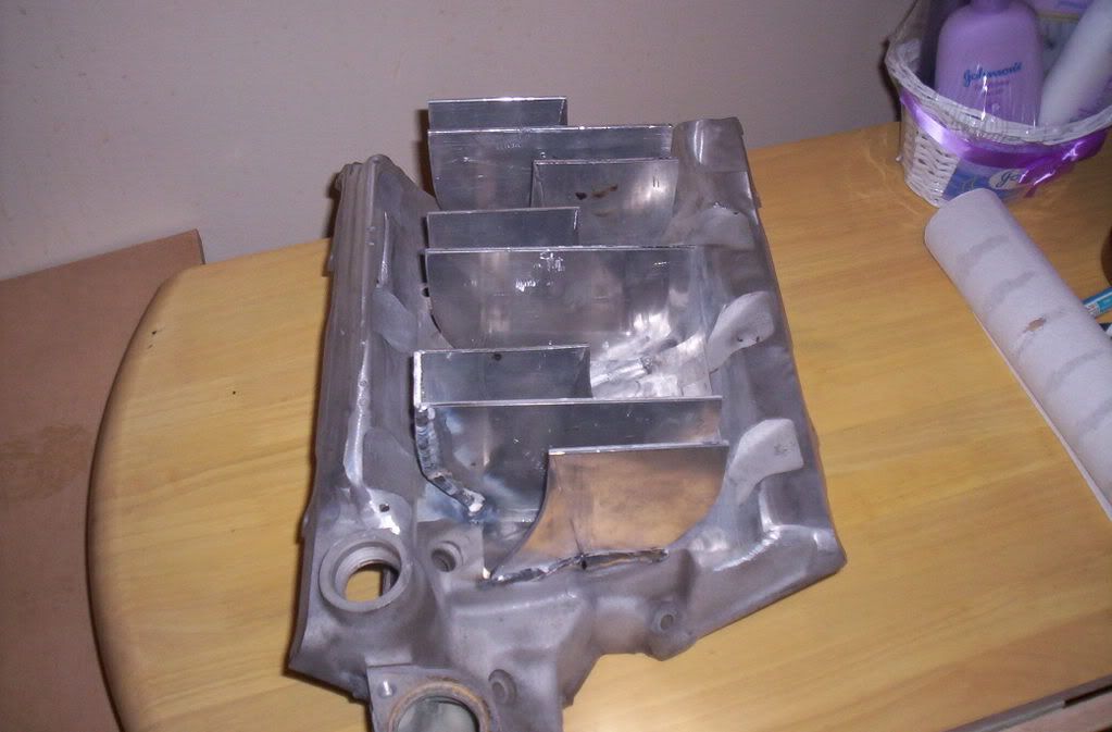
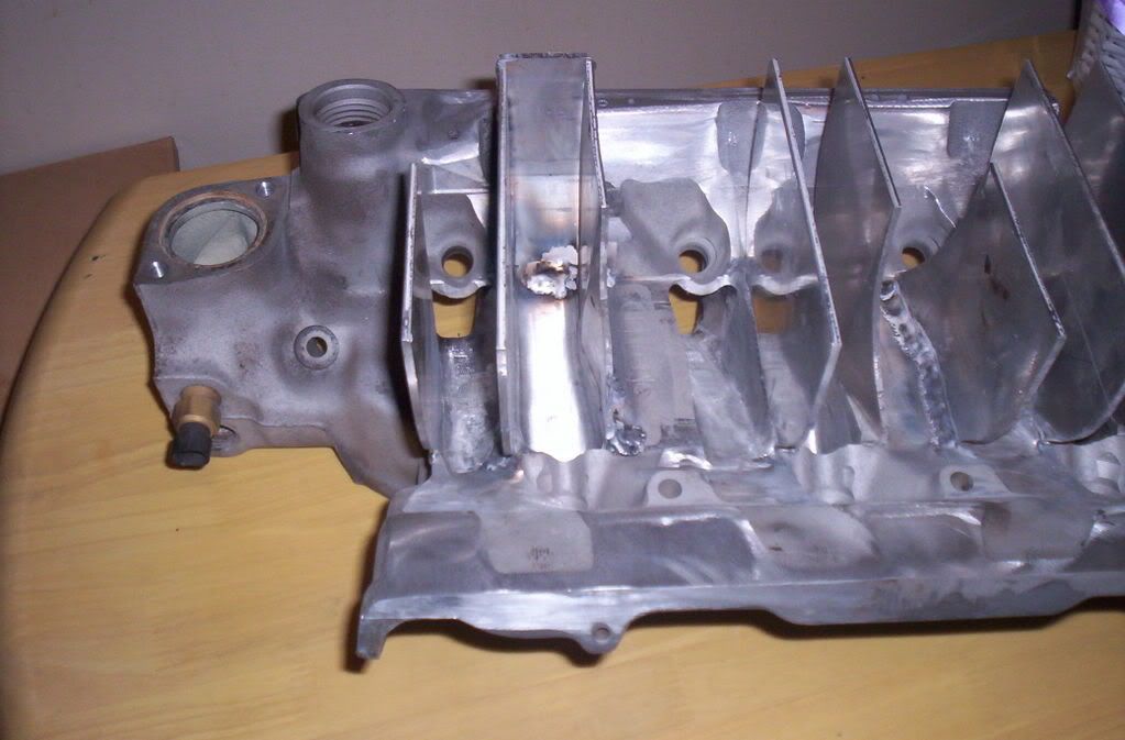
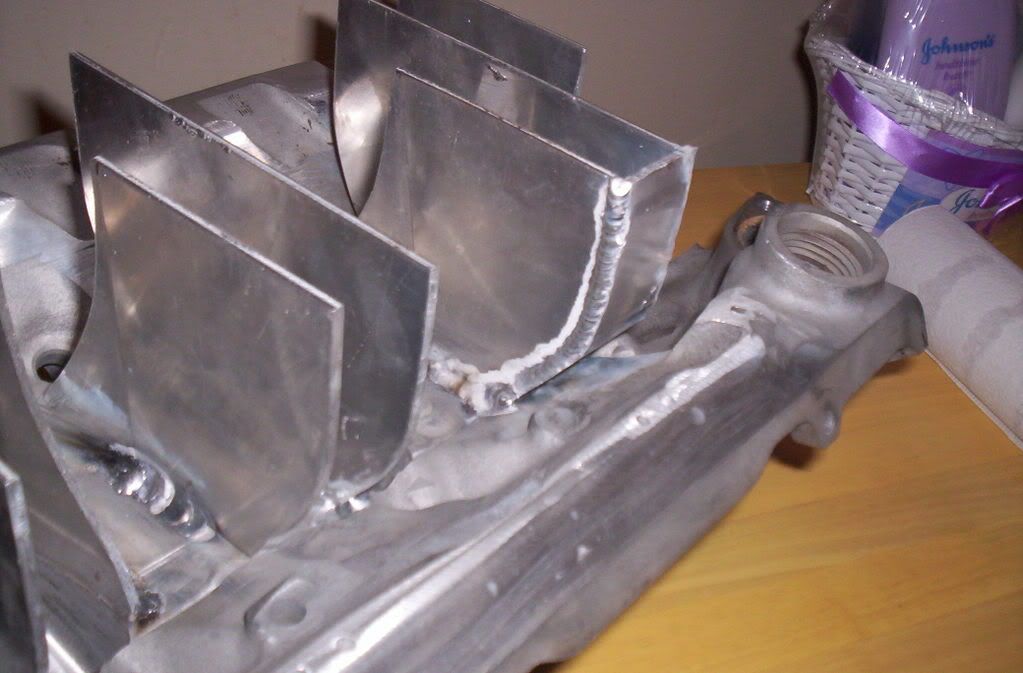
In the picture showing the big gap, are you planning on just welding up the gap and grinding it down? I know it is not a big dral as aluminum is so easy to work with. Was just curious.
In the picture showing the big gap, are you planning on just welding up the gap and grinding it down? I know it is not a big dral as aluminum is so easy to work with. Was just curious.
01-02-2007 | 05:55 PM
#17
Joined: Jun 2001
Posts: 7,980
Likes: 85
From: DC Metro Area
Car: 87TA 87Form 71Mach1 93FleetWB 04Cum
Yea, I think that we�re all a little confused as to where this is ultimately going� I�m assuming that the injectors will still be underneath it, but I�m not sure that I�m seeing where the plenum is going.
Honestly, for boost I�m surprised that you�re creating runners at all.
Honestly, for boost I�m surprised that you�re creating runners at all.
01-02-2007 | 06:06 PM
#18
Thread Starter
Supreme Member
iTrader: (3)
Joined: Dec 2005
Posts: 2,472
Likes: 0
From: Sayreville NJ
Yea, I think that we’re all a little confused as to where this is ultimately going… I’m assuming that the injectors will still be underneath it, but I’m not sure that I’m seeing where the plenum is going.
Honestly, for boost I’m surprised that you’re creating runners at all.
Honestly, for boost I’m surprised that you’re creating runners at all.
if this wasnt a street car the runners would have been alot shorter,but i still need some sort of power down low,so i had to make a few comprimises.what u see is just the runner,ontop of all that i will put a small to mid size plenum.
i shoudl be able to get some more pics up tommorow with some finished runners
btw were u see that gap.it is just that,the runners dont go all the way out to the sides of the manifold,once i get new pics up u will be able to understand it a lil better
 02-23-2007 | 02:46 AM
#26
Joined: Jun 2001
Posts: 7,980
Likes: 85
From: DC Metro Area
Car: 87TA 87Form 71Mach1 93FleetWB 04Cum
IAC� well most GM TB�s use bolt on IAC housings, so it�s easy enough to drill 2 holes in a plate and then bolt on the housing/assembly and run a �external� IAC. Or if you�re a lazy monkey with 4 left thumbs there�s a few companies that sell external IAC housings specifically for running ford TB�s with GM style or aftermarket ecms.

Thread
Thread Starter
Forum
Replies
Last Post
Hotrodboba400
Firebirds for Sale
3
12-10-2019 07:07 PM