
Programming LC-1 NB output?
 01-16-2008, 04:32 PM
#1
Supreme Member

Thread Starter
iTrader: (2)
Join Date: May 2007
Location: right behind you
Posts: 2,574
Likes: 0
Received 0 Likes
on
0 Posts
Car: '85 maro
Engine: In the works...
Transmission: TH700 R4
Axle/Gears: 3.73 posi
Programming LC-1 NB output?
I'm running my car w/ an LC-1 and want to get the NB signal as close to the stock sensor as possible. Right now I have the lower afr set at 13.4/1 @ .850mv and upper afr set at 16/1 @ .050mv with the response set at 1/12 sec. Seems to be running well. Does this sound like good settings? Suggestions?
 01-16-2008, 06:44 PM
#2
Supreme Member
iTrader: (1)
Join Date: Apr 2004
Location: Browns Town
Posts: 3,178
Likes: 0
Received 3 Likes
on
3 Posts
Car: 86 Monte SS (730,$8D,G3,AP,4K,S_V4)
Engine: 406 Hyd Roller 236/242
Transmission: 700R4 HomeBrew, 2.4K stall
Axle/Gears: 3:73 Posi, 7.5 Soon to break
Re: Programming LC-1 NB output?
One of the outputs is defaulted to the stock NB type signal.
Not sure what your asking.
Not sure what your asking.
01-16-2008, 07:32 PM
#3
Member

Join Date: Feb 2004
Location: pa
Posts: 225
Likes: 0
Received 1 Like
on
1 Post
Car: 88 irocz
Engine: b2l 350
Transmission: corvette 4+3
Re: Programming LC-1 NB output?
I'm running my car w/ an LC-1 and want to get the NB signal as close to the stock sensor as possible. Right now I have the lower afr set at 13.4/1 @ .850mv and upper afr set at 16/1 @ .050mv with the response set at 1/12 sec. Seems to be running well. Does this sound like good settings? Suggestions?
Like JP said not sure what you're asking. If your saying your LC1 is swinging between 13.4 and 16.1 while your driving at a steady rate, thats way too much change in the afrs. You've got a lot of adjusting to do on your ve or maf tables depending on which system your working on. You want to achieve 14.7 at all times except in wot. Adjusting the sampling speed of the LC1 just gets you a more acurate afr reading.
01-16-2008, 07:49 PM
#4
Supreme Member
iTrader: (2)

Join Date: Jan 2005
Location: Hurst, Texas
Posts: 10,121
Received 428 Likes
on
368 Posts
Car: 1983 G20 Chevy
Engine: 305 TPI
Transmission: 4L60
Axle/Gears: 14 bolt with 3.07 gears
Re: Programming LC-1 NB output?
Like JP said not sure what you're asking. If your saying your LC1 is swinging between 13.4 and 16.1 while your driving at a steady rate, thats way too much change in the afrs. You've got a lot of adjusting to do on your ve or maf tables depending on which system your working on. You want to achieve 14.7 at all times except in wot. Adjusting the sampling speed of the LC1 just gets you a more acurate afr reading.
01-16-2008, 09:06 PM
#5
Supreme Member
Thread Starter
iTrader: (2)
Join Date: May 2007
Location: right behind you
Posts: 2,574
Likes: 0
Received 0 Likes
on
0 Posts
Car: '85 maro
Engine: In the works...
Transmission: TH700 R4
Axle/Gears: 3.73 posi
Re: Programming LC-1 NB output?
I'm asking how closely it resembles the stock sensor's output, I'm trying to get the signal as close to the stock sensor as possible. Nothing to do with swing points or how my car's running.
01-16-2008, 11:25 PM
#6
Supreme Member
iTrader: (1)

Join Date: Jan 2002
Location: garage
Posts: 4,432
Likes: 0
Received 1 Like
on
1 Post
Engine: 3xx ci tubo
Transmission: 4L60E & 4L80E
Re: Programming LC-1 NB output?
The commercial high selling WBO2 controllers are behind the times. The DIY JAW WBO2 is the only controller that I know of that allows you to program the NBO2 settings. It might be worth upgrading for the $55 shipped that they charge.
If you make the NBO2 output more linear in the 0-1v range then you can tune the closed loop O2 tables much better.
The JAW WBO2 is the next best thing to the DIY-WBO2 in my opinion. The controller costs $55 and the sensor is another $55. For about $120 you have a complete WBO2 setup that is programmable and includes data logging software for free.
01-17-2008, 02:35 PM
#7
Supreme Member
Thread Starter
iTrader: (2)
Join Date: May 2007
Location: right behind you
Posts: 2,574
Likes: 0
Received 0 Likes
on
0 Posts
Car: '85 maro
Engine: In the works...
Transmission: TH700 R4
Axle/Gears: 3.73 posi
Re: Programming LC-1 NB output?
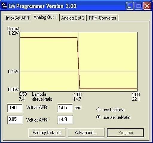
Since a picture's worth a thousand words here's a shot of what I currently have programmed into my LC-1. How close to the stock sensor's output is this?
Last edited by bl85c; 01-17-2008 at 06:16 PM.
Trending Topics
01-17-2008, 06:13 PM
#8
Supreme Member
iTrader: (1)
Join Date: Apr 2004
Location: Browns Town
Posts: 3,178
Likes: 0
Received 3 Likes
on
3 Posts
Car: 86 Monte SS (730,$8D,G3,AP,4K,S_V4)
Engine: 406 Hyd Roller 236/242
Transmission: 700R4 HomeBrew, 2.4K stall
Axle/Gears: 3:73 Posi, 7.5 Soon to break
Re: Programming LC-1 NB output?
From the LC-1 manual
"As factory programmed the first output simulates a typical narrow band oxygen sensor.
The second output is programmed to output between 0 V for an AFR of 7.35 (gasoline) and 5.0V for an AFR of 22.39.
Other curves of course are easily programmable"
The "factory defaults" buton will put that output to be the settings for the NB.
I never looked to see what the default values were but my notes I have the Simulated set to 14:1 AFR = .103 Volts, 15:1 AFR = 1.099 volts.
that may be the default.
01-17-2008, 06:22 PM
#9
Supreme Member
Thread Starter
iTrader: (2)
Join Date: May 2007
Location: right behind you
Posts: 2,574
Likes: 0
Received 0 Likes
on
0 Posts
Car: '85 maro
Engine: In the works...
Transmission: TH700 R4
Axle/Gears: 3.73 posi
Re: Programming LC-1 NB output?
Yep, that's the default values, but I don't think they're very accurate. I suppose it doesn't matter much as long as stoich is set at .45v but I'd like it to be as accurate as possible. I read somewhere that the 'full on to full off' range of the stock sensor is about 14.9 to 14.5 AFR, so those are what I used. Here's the chart I used to come up with those values.

Last edited by bl85c; 01-17-2008 at 06:29 PM.
01-17-2008, 06:39 PM
#10
Supreme Member
iTrader: (1)
Join Date: Apr 2004
Location: Browns Town
Posts: 3,178
Likes: 0
Received 3 Likes
on
3 Posts
Car: 86 Monte SS (730,$8D,G3,AP,4K,S_V4)
Engine: 406 Hyd Roller 236/242
Transmission: 700R4 HomeBrew, 2.4K stall
Axle/Gears: 3:73 Posi, 7.5 Soon to break
Re: Programming LC-1 NB output?
Like junkcltr says, using the linear output of a better sensor will allow you to tune your tables to provide the AFR you desire.
Setting up a voltage will equal an AFR will not work.
If the simulated NB is truly a straight line then the "Window" and the high/low table limits can be shrunk to provide tighter control of the bouncing/switching.
With the tightening of the values, the gains will need to change also to respond to the smaller control range.
In any case, the bouncing high to low (no matter what the voltage) is what you want to get the control over, not attempting to maintain a single AFR but bouncing either side of it to get the best avaerage you can.
01-17-2008, 08:19 PM
#11
Supreme Member
Thread Starter
iTrader: (2)
Join Date: May 2007
Location: right behind you
Posts: 2,574
Likes: 0
Received 0 Likes
on
0 Posts
Car: '85 maro
Engine: In the works...
Transmission: TH700 R4
Axle/Gears: 3.73 posi
Re: Programming LC-1 NB output?
Great suggestions, but it's not exactly what I'm looking for.
I'm using the WB output to do the actual tuning and the NB output to run my car. The second graph is a plot of the stock sensor's output vs actual afr. It's kinda hard to read since there's so many stray datapoints, but I can tell what the overall trend is.
From what I understand- in the real world the stock sensor's output varies with temperature, backpressure and other things, but the LC-1 doesn't have provisions to simulate that so I need to do the best I can with what I've got. So how close do you think what I've programmed is to what the stock sensor's output is?
Last edited by bl85c; 01-17-2008 at 08:30 PM.
01-17-2008, 11:28 PM
#12
Supreme Member
iTrader: (1)
Join Date: Jan 2002
Location: garage
Posts: 4,432
Likes: 0
Received 1 Like
on
1 Post
Engine: 3xx ci tubo
Transmission: 4L60E & 4L80E
Re: Programming LC-1 NB output?
Read what JP86SS said a few times. With a programmed more linear NBO2 curve you can target AFRs very accurately. If your intent is to target a certain AFR in closed loop this will work extremely well.
01-18-2008, 10:25 AM
#13
Supreme Member
Thread Starter
iTrader: (2)
Join Date: May 2007
Location: right behind you
Posts: 2,574
Likes: 0
Received 0 Likes
on
0 Posts
Car: '85 maro
Engine: In the works...
Transmission: TH700 R4
Axle/Gears: 3.73 posi
Re: Programming LC-1 NB output?
Sometimes I need to re-read things a couple times to get it through my head. 
So by tightening it to say, 14.8 and 14.6 (or closer) it should target stoich better than the original sensor. Isn't that what the 'lower/upper 0 error for slow O2 vs airflow' tables are for? By tightening both would I be able to get it to run at a constant 14.7 in closed loop (without a cat)?
So by tightening it to say, 14.8 and 14.6 (or closer) it should target stoich better than the original sensor. Isn't that what the 'lower/upper 0 error for slow O2 vs airflow' tables are for? By tightening both would I be able to get it to run at a constant 14.7 in closed loop (without a cat)?
01-23-2008, 11:55 AM
#14
Senior Member
Join Date: Jun 2007
Location: Akron, Ohio
Posts: 600
Likes: 0
Received 0 Likes
on
0 Posts
Car: 87 Suburban 2500
Engine: 455 Wildcat ( somewhat modified ))
Transmission: TH400 ( for now )
Axle/Gears: 4.10 ( for now )
Re: Programming LC-1 NB output?
How did you deal with the idea that the outputs are AC, and not DC 0-5 V ?
Worse, that the software to run it just seems to "grab" whatever the current number happens to be, even though it's changing from 10-20 at a very rapid rate ? ( as is the output line )
Now that I've changed the design ( twice ) it's almost usable, but since its own cal value is all over the map, I'm not sure I'd trust it as authoritative.
Bought it as a toy, strictly. I'm not at all disappointed for the money, but.....
True, if you can get a usable, accurate output, it does allow programming any curve you want to represent anything you want, but I'm real sure I'm not trusting my engine to it any time soon.
Maybe, but only after some independent confirmation of accuracy and repeatability. It's not there yet.
01-23-2008, 12:25 PM
#15
Supreme Member
iTrader: (1)
Join Date: Jan 2002
Location: garage
Posts: 4,432
Likes: 0
Received 1 Like
on
1 Post
Engine: 3xx ci tubo
Transmission: 4L60E & 4L80E
Re: Programming LC-1 NB output?
The outputs are square wave PWM with a low pass filter. I use the Vout2 output only. It is driven by the LM324 OP AMP buffer. Vout1 is LPF from the AVR chip (no buffer).
So, the LPF turns the square wave (you are calling it AC which is false) into a static DC level with a slight sine component. You can change the LPF via the output capacitor and resistor. Decreasing the LPF cutoff with decrease the sine noise, but slow down the ckt response.
What software grabs the current number? Are you talking about the logging software? How did you "change the design"? Did you drop in your own AVR? Play with the R's & C's, or adjust the logging software?
I use the ECM to log the Vout2 value. I use a LPF in the ECM code with a .125 coefficient. I don't use it as a toy. It is used as the full time closed loop sensor. It is installed on a stock 305ci TPI with up to 12 PSI of boost and it seems to report as accurate as the DIY WBO2 did. The engine has been up to 16 PSI and it seems to read properly. Also, not much room for error at 16 PSI with a stock 305ci TPI.
01-23-2008, 12:31 PM
#16
Supreme Member
iTrader: (1)
Join Date: Jan 2002
Location: garage
Posts: 4,432
Likes: 0
Received 1 Like
on
1 Post
Engine: 3xx ci tubo
Transmission: 4L60E & 4L80E
Re: Programming LC-1 NB output?
Two things that I don't like about the JAW:
No available heater ckt LED points (need to add yourself)
Ri measurement cap. is an electrolytic and should be a non-polarized cap.
Heater ckt heatsink is too small
R's & C's for PWM LPF could be smaller.
Ip measurement is not done using an current sense amp (noisy measurements, bias, etc)
No code available (can't see if the normal algo. sleeps when the Ip msrmnt is done)
For $55 shipped it seems well worth it to me.
01-23-2008, 12:36 PM
#17
Supreme Member
iTrader: (1)
Join Date: Jan 2002
Location: garage
Posts: 4,432
Likes: 0
Received 1 Like
on
1 Post
Engine: 3xx ci tubo
Transmission: 4L60E & 4L80E
Re: Programming LC-1 NB output?
I played around with the LPF filter in the ECM for a while. The lag filter with a .125 coefficient seems to work well eliminating noise and providing a good transient response. I lag filter it using only one 8_bit value to save RAM. I don't use the stock ECM lag filter function. I use the carry bit as the sign bit and the 8_bit value as the magnitude.
01-23-2008, 01:29 PM
#18
Senior Member
Join Date: Jun 2007
Location: Akron, Ohio
Posts: 600
Likes: 0
Received 0 Likes
on
0 Posts
Car: 87 Suburban 2500
Engine: 455 Wildcat ( somewhat modified ))
Transmission: TH400 ( for now )
Axle/Gears: 4.10 ( for now )
Re: Programming LC-1 NB output?
The outputs are square wave PWM with a low pass filter. I use the Vout2 output only. It is driven by the LM324 OP AMP buffer. Vout1 is LPF from the AVR chip (no buffer).
So, the LPF turns the square wave (you are calling it AC which is false) into a static DC level with a slight sine component.
So, the LPF turns the square wave (you are calling it AC which is false) into a static DC level with a slight sine component.
You are correct, it is PWM square, 32kHz 5V P-P. The existing components round the edges, but do not leave anything close to a static DC, ( except at the rails ) and the component is neither sine, nor slight.
Of course, if one uses it with a DVM, or a 260, the averaging in the meter hides all that. First time out with EBL was a whole 'nother thing when I graphed it, which is how I initially found it. EBL is fast enough that it showed nothing like an AFR trace, but more like a narrow band, except with a full range swing.
I benched the thing, recalc'd the LPF into the follower, breadboard, scope, and settled on what appears to be acceptable. Might yet change some of the stuff to be able to work below freezing. As it is, I'm not certain It'll work in winter, but it might.
I use the ECM to log the Vout2 value. I use a LPF in the ECM code with a .125 coefficient. I don't use it as a toy. It is used as the full time closed loop sensor. It is installed on a stock 305ci TPI with up to 12 PSI of boost and it seems to report as accurate as the DIY WBO2 did. The engine has been up to 16 PSI and it seems to read properly. Also, not much room for error at 16 PSI with a stock 305ci TPI.
That you can report such good luck is VERY encouraging to me, but I'm not sure I'll recommend it to the average gear-head as a ready-for-prime-time tool.
I bought it with full knowledge and expectation as a toy, and don't regret the purchase by any means, but I'm hardly typical.

Agreed ! That's one of the first mods I did.
Oh, and DON'T short ( accidentally or otherwise ) that heat sink to the regulator adjacent !!
I'll be adding a fuse, and some polarity and surge protection ( only has a low power 18 volt zener that shorts and incinerates traces as-is ) as well as a few other things, but over-all it's not terrible for what it is.
He's already said in his forum that his objective was cheap, so that's why there's no fuse, among other things.
He's already refused to provide a print, or code, though someone has done a Linux hack to run with Mono. Suits me fine. The schematic isn't a big deal, and I'm only using his software to write the lambda/AFR vs voltage table anyway.
I'm not at all sorry I bought it, would do so again, but I wouldn't recommend it if you don't have a solid electronics background, and can recognize design deficiencies.
----------
Noise left over from the filtering, absolutely ! No question. Scoped, checked, and proven in steady test gas.
Last edited by Cflick; 01-23-2008 at 01:31 PM. Reason: Automerged Doublepost

Thread
Thread Starter
Forum
Replies
Last Post
TMZIrocZ350
Engine/Drivetrain/Suspension Parts for Sale
1
10-07-2015 12:09 PM
[CA] 700R4 trans & parts
6998poncho
Engine/Drivetrain/Suspension Parts for Sale
0
09-25-2015 02:56 PM
airflow, bounces, gasoline, high, lc, lc1, lm324, low, o2, outputs, programing, programmer, programming, slow