
Cylinder select netres values?
 02-09-2006, 05:51 PM
#1
Member
Thread Starter
iTrader: (2)

Join Date: Jun 2002
Posts: 248
Likes: 0
Received 0 Likes
on
0 Posts
Cylinder select netres values?
Hey everyone,
Question that I couldn't find the answer to... I need to turn some v6 memcals into v8 memcals. Without having to go through the gory details, just trust me when I say it's easier for me. Basically my problem was, I need a V8 memcal with a 3.1 knock sensor board.
But anyways, on the 1227730, what resistor(s)/pins of the netres correspond to the "hardware" cylinder select? I have both v6 and v8 memcals to double check...
 02-09-2006, 06:41 PM
#2
Supreme Member

iTrader: (1)

Join Date: Jan 2002
Location: garage
Posts: 4,432
Likes: 0
Received 1 Like
on
1 Post
Engine: 3xx ci tubo
Transmission: 4L60E & 4L80E
Re: Cylinder select netres values?
Originally posted by ryan.h
Without having to go through the gory details, just trust me when I say it's easier for me. Basically my problem was, I need a V8 memcal with a 3.1 knock sensor board.
Without having to go through the gory details, just trust me when I say it's easier for me. Basically my problem was, I need a V8 memcal with a 3.1 knock sensor board.
02-09-2006, 07:01 PM
#3
Member
Thread Starter
iTrader: (2)
Join Date: Jun 2002
Posts: 248
Likes: 0
Received 0 Likes
on
0 Posts
https://www.thirdgen.org/techbb2/sho...res+cyl+select
Last post, somebody might have this document... I'll PM him as well.
Last post, somebody might have this document... I'll PM him as well.
02-09-2006, 08:51 PM
#4
TGO Supporter

Join Date: Aug 2001
Location: NJ/PA
Posts: 1,008
Likes: 0
Received 0 Likes
on
0 Posts
Car: Yes
Engine: Many
Transmission: Quite a few
Hey, I got your PM. The pins I was talking about in those posts weren't for the cylinder select pins. They were an actual resistor value tied to ground to an unused pin on the knock board, which specified what the tuned frequency was for any knock filter board, and the application. Since there aren't any markings on it, I guess the factory gave a resistive ID to them all. I put this document somewhere, I'll have to dig it up, though maybe I didn't and just gave it to anyone who PM'ed me long ago. I figured this out from two or three documents that were on the ftp site for diy-efi.org.
the cylinder select pin, however, is on the memcal, in the two small 'chips' under the knock circuit. I do have this info somewhere, probably from something in diy-efi.org, or I think I recall grumpy posting something about this.
If you rewire the 3.1 memcal, bear in mind that the limp home settings may not work for your application, it will think its a v-8 and the knock will work for whatever you plan to do, but if the prom ever fails, I don't know what the outcome will be.
i started to decipher this stuff awhile back, but the res network doesn't make sense in alot of cases, and trying to run the equations for the network seemed crazy, so being the lazy guy I am, I left it at that.
sorry I'm not much help at this point, I'll dig around and see what I can find, but it might take a couple days.
02-09-2006, 09:28 PM
#5
Supreme Member
iTrader: (1)
Join Date: Apr 2004
Location: Browns Town
Posts: 3,178
Likes: 0
Received 3 Likes
on
3 Posts
Car: 86 Monte SS (730,$8D,G3,AP,4K,S_V4)
Engine: 406 Hyd Roller 236/242
Transmission: 700R4 HomeBrew, 2.4K stall
Axle/Gears: 3:73 Posi, 7.5 Soon to break
There was a note by Rbob in this thread.
https://www.thirdgen.org/techbb2/sho...ghlight=select
May be only for TBI but thought it might be useful to you.
Jp
https://www.thirdgen.org/techbb2/sho...ghlight=select
May be only for TBI but thought it might be useful to you.
Jp
Last edited by JP86SS; 02-09-2006 at 09:35 PM.
02-09-2006, 09:33 PM
#6
TGO Supporter
Join Date: Mar 2004
Location: Monument, Colorado
Posts: 66
Likes: 0
Received 0 Likes
on
0 Posts
Car: 89 C2500
Engine: ZZ838, MPFI, Whipple, & 7749 ECU
Transmission: 700R4
Axle/Gears: 4.10
When I was working with the 1227749 and TBI a while back, I found CAL56 (memcal pin 56) was used for cylinder select. I believe I determined this by looking at the ECM schematics on Ludis' site. He's got a ton of valuable info there!
Oh, the 1227749 is very similar to a 1227730. Currently, I'm using a '730 AUJP V8 memcal on my '749 running MPFI.
Oh, the 1227749 is very similar to a 1227730. Currently, I'm using a '730 AUJP V8 memcal on my '749 running MPFI.
Last edited by 89C2500; 02-09-2006 at 09:39 PM.
02-09-2006, 09:33 PM
#7
Supreme Member
iTrader: (1)
Join Date: Apr 2004
Location: Browns Town
Posts: 3,178
Likes: 0
Received 3 Likes
on
3 Posts
Car: 86 Monte SS (730,$8D,G3,AP,4K,S_V4)
Engine: 406 Hyd Roller 236/242
Transmission: 700R4 HomeBrew, 2.4K stall
Axle/Gears: 3:73 Posi, 7.5 Soon to break
Also found this in my junk, Authors name is on it.
I never confirmed how different it was to a V8.
Please post what you find.
THX
I never confirmed how different it was to a V8.
Please post what you find.
THX
Trending Topics
02-09-2006, 09:44 PM
#8
Member
Thread Starter
iTrader: (2)
Join Date: Jun 2002
Posts: 248
Likes: 0
Received 0 Likes
on
0 Posts
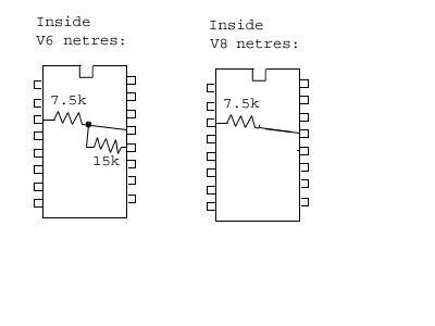
Maybe I'm missing something here.. There are 2 chips under the knock filter board. I assumed they were both "netres"... There's a 14pin and a 16pin. Is the 16 pin the one that has to do with the cylinder select, and the 14 pin the "limp home mode"?
btw- if indeed it is CAL56, then that simple 7.5k resistor is all that needs to be changed. In the v6 memcal I have here, that is a 15k resistor. I can check tomorrow on the value in the V8 memcal, and do some experimentation with the value if it too shows 7.5k....
btw- if indeed it is CAL56, then that simple 7.5k resistor is all that needs to be changed. In the v6 memcal I have here, that is a 15k resistor. I can check tomorrow on the value in the V8 memcal, and do some experimentation with the value if it too shows 7.5k....
Last edited by ryan.h; 02-09-2006 at 09:55 PM.
02-09-2006, 09:54 PM
#9
TGO Supporter
Join Date: Mar 2004
Location: Monument, Colorado
Posts: 66
Likes: 0
Received 0 Likes
on
0 Posts
Car: 89 C2500
Engine: ZZ838, MPFI, Whipple, & 7749 ECU
Transmission: 700R4
Axle/Gears: 4.10
CAL56 would be on the 16 pin chip. Check out the memcal doc found here ftp.diy-efi.org/uploads/memcal.pdf
The netres in that document is from a twin turbo 3.6 liter V6.
The netres in that document is from a twin turbo 3.6 liter V6.
02-09-2006, 09:57 PM
#10
Member
Thread Starter
iTrader: (2)
Join Date: Jun 2002
Posts: 248
Likes: 0
Received 0 Likes
on
0 Posts
Originally posted by 89C2500
CAL56 would be on the 16 pin chip. Check out the memcal doc found here ftp.diy-efi.org/uploads/memcal.pdf
The netres in that document is from a twin turbo 3.6 liter V6.
CAL56 would be on the 16 pin chip. Check out the memcal doc found here ftp.diy-efi.org/uploads/memcal.pdf
The netres in that document is from a twin turbo 3.6 liter V6.
02-09-2006, 10:10 PM
#11
TGO Supporter
Join Date: Mar 2004
Location: Monument, Colorado
Posts: 66
Likes: 0
Received 0 Likes
on
0 Posts
Car: 89 C2500
Engine: ZZ838, MPFI, Whipple, & 7749 ECU
Transmission: 700R4
Axle/Gears: 4.10
Originally posted by ryan.h
thanks, I have that document and the 749(?) schematic, but the 749 schematic seems largely incomplete. It doesn't show where any of the memcal pins lead to, aside from a select few like the knock sensor input/output and power pins.
thanks, I have that document and the 749(?) schematic, but the 749 schematic seems largely incomplete. It doesn't show where any of the memcal pins lead to, aside from a select few like the knock sensor input/output and power pins.
02-09-2006, 10:23 PM
#12
Member
Thread Starter
iTrader: (2)
Join Date: Jun 2002
Posts: 248
Likes: 0
Received 0 Likes
on
0 Posts
Wow, I had no idea! Thanks!!
measurements on the v6 memcal confirm what is shown in the memcal.pdf document, 15k to Vnet, and 7.5k to ground.
1/3 voltage divider = v6... I'm guessing maybe 1/4 = v8? bah... I'd better pull the v8 memcal out of my car, because this will be bugging me all night.")
measurements on the v6 memcal confirm what is shown in the memcal.pdf document, 15k to Vnet, and 7.5k to ground.
1/3 voltage divider = v6... I'm guessing maybe 1/4 = v8? bah... I'd better pull the v8 memcal out of my car, because this will be bugging me all night.
Last edited by ryan.h; 02-09-2006 at 10:32 PM.
02-09-2006, 10:40 PM
#13
Member
Thread Starter
iTrader: (2)
Join Date: Jun 2002
Posts: 248
Likes: 0
Received 0 Likes
on
0 Posts
ok, V8 memcal still shows the 7.5k resistor to ground, however, the 15k resistor to Vnet is now nonexistant.
So, turning a v6 into a v8 memcal seems simple, just cut the CAL56 and put a 7.5k resistor to CAL53, or on the 16 pin chip itself, put a 7.5k resistor from pin 3 to pin 13. *edit: err, pin 13 no longer has any connection to anything because you physically removed it. I meant a 7.5k resistor from pin 3 to the pin socket on the memcal where pin 13 used to be.
Thanks everyone, couldn't have done it without ya! I'll check it to confirm that I get no error codes later...
Last edited by ryan.h; 02-09-2006 at 10:43 PM.


 02-17-2006, 02:40 PM
#19
You don't go to the yards enough.
I have those laying around.
I let the 1 yr old entertain himself with one.
Pending your results I may need to take it back.
Figuring this out has been on my todo list for a while.
I have those laying around.
I let the 1 yr old entertain himself with one.
Pending your results I may need to take it back.
Figuring this out has been on my todo list for a while.
02-17-2006, 03:26 PM
#20
Member
Thread Starter
iTrader: (2)
Join Date: Jun 2002
Posts: 248
Likes: 0
Received 0 Likes
on
0 Posts
Don't have any u-pull-it's here... they're conveniently pocket sized... not that I condone such an activity. 
I should be getting one shortly though, if nobody posts the results before me.
I should be getting one shortly though, if nobody posts the results before me.
02-26-2006, 10:07 AM
#21
Junior Member

Join Date: Apr 2005
Location: Virginia
Posts: 98
Likes: 0
Received 0 Likes
on
0 Posts
Car: 1969 Z28
Engine: 406 TPI
Transmission: Tremec TKO 600
Axle/Gears: 3.31
Cylinder select netres values?
ryan.h,
Very interesting subjet. Have you had any success in testing out this idea? I'd like to be able to convert V6 memcals for use in my V8 project and all the EFI community would benefit from "cheaper more plentiful" memcals.
VR,
DZcode
Very interesting subjet. Have you had any success in testing out this idea? I'd like to be able to convert V6 memcals for use in my V8 project and all the EFI community would benefit from "cheaper more plentiful" memcals.
VR,
DZcode
03-11-2006, 09:28 PM
#23
TGO Supporter
Join Date: Mar 2004
Location: Monument, Colorado
Posts: 66
Likes: 0
Received 0 Likes
on
0 Posts
Car: 89 C2500
Engine: ZZ838, MPFI, Whipple, & 7749 ECU
Transmission: 700R4
Axle/Gears: 4.10
Originally posted by ryan.h
ok, V8 memcal still shows the 7.5k resistor to ground, however, the 15k resistor to Vnet is now nonexistant.
So, turning a v6 into a v8 memcal seems simple, just cut the CAL56 and put a 7.5k resistor to CAL53, or on the 16 pin chip itself, put a 7.5k resistor from pin 3 to pin 13. *edit: err, pin 13 no longer has any connection to anything because you physically removed it. I meant a 7.5k resistor from pin 3 to the pin socket on the memcal where pin 13 used to be.
Thanks everyone, couldn't have done it without ya! I'll check it to confirm that I get no error codes later...
03-11-2006, 09:37 PM
#24
TGO Supporter
Join Date: Mar 2004
Location: Monument, Colorado
Posts: 66
Likes: 0
Received 0 Likes
on
0 Posts
Car: 89 C2500
Engine: ZZ838, MPFI, Whipple, & 7749 ECU
Transmission: 700R4
Axle/Gears: 4.10
Originally posted by 89C2500
I did this modification today to a '749 BBZB memcal. Instead of using ground at CAL53, I used CAL62 which is also a ground. Works out great!
I did this modification today to a '749 BBZB memcal. Instead of using ground at CAL53, I used CAL62 which is also a ground. Works out great!
03-11-2006, 11:44 PM
#25
Supreme Member
iTrader: (1)
Join Date: Jan 2002
Location: garage
Posts: 4,432
Likes: 0
Received 1 Like
on
1 Post
Engine: 3xx ci tubo
Transmission: 4L60E & 4L80E
Those surface mount resistors & capacitors are going to be hard to change to get the knock sensor filter to work properly. Laquer thinner/Acetone works well for removing the conformal coating.
03-12-2006, 11:33 AM
#26
TGO Supporter
Join Date: Mar 2004
Location: Monument, Colorado
Posts: 66
Likes: 0
Received 0 Likes
on
0 Posts
Car: 89 C2500
Engine: ZZ838, MPFI, Whipple, & 7749 ECU
Transmission: 700R4
Axle/Gears: 4.10
Originally posted by junkcltr
Those surface mount resistors & capacitors are going to be hard to change to get the knock sensor filter to work properly. Laquer thinner/Acetone works well for removing the conformal coating.
Those surface mount resistors & capacitors are going to be hard to change to get the knock sensor filter to work properly. Laquer thinner/Acetone works well for removing the conformal coating.
I couldn't tell any difference between the two when testing them in the vehicle. I test with a BIN that had enough timing in low RPM & high load areas to induce inaudible knock.
Anyway, I've actually removed the ESC filter board and have wired in an LT4 ESC module. This is working much better for my setup. The roller rocker valvetrain I'm running is quite noisy and I was having issues with false knock. I tried the commonly posted resistor network fix...but that really didn't help. I've been running the LT4 ESC module on the AUJP memcal for about a month now. I just moved it to the BBZB V8-adapted memcal yesterday. Here's how I installed it on the AUJP memcal (oh...can't use the blue cover any more
 )
03-13-2006, 12:46 AM
)
03-13-2006, 12:46 AM
#27
Supreme Member
iTrader: (1)
Join Date: Jan 2002
Location: garage
Posts: 4,432
Likes: 0
Received 1 Like
on
1 Post
Engine: 3xx ci tubo
Transmission: 4L60E & 4L80E
I never measured Rs & Cs on a 4.3 memcal KS module. The bore volume theory makes sense.
I like the LT4/AUJP memcal. I looked into the LT4 & LT1 knock modules a while ago. I seem to remember something being up with the fact that some LT1 knock modules are designed for 2 knock sensors and some are designed for 1 knock sensor. I can't seem to remember what the LT4 knock module was designed for. I thought the LT4 was designed for 2 knock sensors. Could be wrong though. Didn't the Corvette & Caprice get two knock sensors and the F-body got one.
It always seemed odd to me that F-body LT1 users (one knock sensor) would throw in a LT4 knock module (two knock sensors). Many claim that the LT4 detects "true knock" due to a better design.......but it is really just because of the resistance change. I wonder if the LT4 is better by design for detecting "true knock".
03-13-2006, 09:34 AM
#28
TGO Supporter
Join Date: Mar 2004
Location: Monument, Colorado
Posts: 66
Likes: 0
Received 0 Likes
on
0 Posts
Car: 89 C2500
Engine: ZZ838, MPFI, Whipple, & 7749 ECU
Transmission: 700R4
Axle/Gears: 4.10
Originally posted by junkcltr
I thought the LT4 was designed for 2 knock sensors. Could be wrong though. Didn't the Corvette & Caprice get two knock sensors and the F-body got one.
I thought the LT4 was designed for 2 knock sensors. Could be wrong though. Didn't the Corvette & Caprice get two knock sensors and the F-body got one.
I tested it out on my ECM bench before putting in the the vehicle. It was difficult to tell the difference in sensitivity on the bench, but I see a big difference in the vehicle. Now...am I just detecting "true" knock, OR am I filtering out some true knock, that's the $100 question!
03-13-2006, 10:59 AM
#29
Supreme Member
iTrader: (1)
Join Date: Jan 2002
Location: garage
Posts: 4,432
Likes: 0
Received 1 Like
on
1 Post
Engine: 3xx ci tubo
Transmission: 4L60E & 4L80E
Originally posted by 89C2500
According to the AC Delco database, the 96 LT4 Vette used one knock sensor.
According to the AC Delco database, the 96 LT4 Vette used one knock sensor.
Knock is funny thing. I don't think you can ever really know, but by the sounds of it you have an ideal knock sense mechanism with currently available hardware.
03-13-2006, 12:00 PM
#30
Member
Thread Starter
iTrader: (2)
Join Date: Jun 2002
Posts: 248
Likes: 0
Received 0 Likes
on
0 Posts
I have specs on several knock sensors if anybody's interested...
Part #........Fcenter Hz.........Bandwidth Hz......Magnitude V
=============================================================
KS2..........6,306 +/- 370.....130 +/- 129.........1.20 +/- 1.00 (5.0TBI)
KS3..........6,346 +/- 276.....132 +/- 129..........0.37 +/- .25 (5.0TPI and 3.1)
Part #........Fcenter Hz.........Bandwidth Hz......Magnitude V
=============================================================
KS2..........6,306 +/- 370.....130 +/- 129.........1.20 +/- 1.00 (5.0TBI)
KS3..........6,346 +/- 276.....132 +/- 129..........0.37 +/- .25 (5.0TPI and 3.1)
01-13-2009, 11:39 PM
#31
Junior Member

Join Date: Sep 2008
Posts: 32
Likes: 0
Received 0 Likes
on
0 Posts
Re: Cylinder select netres values?
I'm just a little confused....
Can pin 12 be cut and just leave the 7.5 resistor just like it is installed between pin 3 and 13 inside the chip?
----------
did you cut the pin on cal56? If you did, where is the resistor installed...on the chip side of the cut or the out side of the cut?
Does that make sense? I just don't want to screw up...lol
Can pin 12 be cut and just leave the 7.5 resistor just like it is installed between pin 3 and 13 inside the chip?
----------
Does that make sense? I just don't want to screw up...lol
Last edited by kik_start; 01-13-2009 at 11:42 PM. Reason: Automerged Doublepost
 01-14-2009, 10:30 AM
#34
Supreme Member
iTrader: (1)
Join Date: Jan 2002
Location: garage
Posts: 4,432
Likes: 0
Received 1 Like
on
1 Post
Engine: 3xx ci tubo
Transmission: 4L60E & 4L80E
Re: Cylinder select netres values?
kik_start,
What RBob and jwscab said is correct. You want to connect pin 13 (cyl select) to pin 10 (ground). That should remove the code 41 error and fire the injectors properly.
You need to know how to count the pins on the chip to find pins 13 and 10.
The picture in the earlier posts shows where the pins 13 and 10 are located.
I did take a picture for you of the memcal pins, but I do not have a means of posting them today.


 02-02-2009, 08:33 AM
#39
TGO Supporter
Join Date: Aug 2001
Location: NJ/PA
Posts: 1,008
Likes: 0
Received 0 Likes
on
0 Posts
Car: Yes
Engine: Many
Transmission: Quite a few
Re: Cylinder select netres values?
good, glad it worked out.
just remember, the knock circuit probably won't work. It might work a little bit under extreme knock, so just be cautious.
if the prom falls out or get's flaky, or otherwise puts the ecm into limp home mode, the engine won't run properly, so if see that, shut it down asap and fix it, don't try limping it home.
09-02-2010, 03:20 PM
#41
Junior Member

Join Date: Jun 2010
Posts: 21
Likes: 0
Received 0 Likes
on
0 Posts
Re: Cylinder select netres values?
Ok I know how to count the pins on the chip correctly but I need to make sure I get this correct.
So I cut the pin 56 from the chip which is pin 13 directly on the chip (netres) Now I do I leave the pin not connected to anything off the chip and runa jumper from the socket on the board to a ground or am I suppose to run the little leg (pin) from the chip and ground it?
Example on the left i didnt cut the pin just ran a jumper wire. Ex on right I cut the little prong Pin 13 on the chip and ran a jumper from where it plugs in the board to pin 10 which is ground. Which one is correct?

Uploaded with ImageShack.us
09-02-2010, 04:59 PM
#42
Supreme Member
iTrader: (1)
Join Date: Jan 2002
Location: garage
Posts: 4,432
Likes: 0
Received 1 Like
on
1 Post
Engine: 3xx ci tubo
Transmission: 4L60E & 4L80E
Re: Cylinder select netres values?
Ok I know how to count the pins on the chip correctly but I need to make sure I get this correct.
So I cut the pin 56 from the chip which is pin 13 directly on the chip (netres) Now I do I leave the pin not connected to anything off the chip and runa jumper from the socket on the board to a ground or am I suppose to run the little leg (pin) from the chip and ground it?
Example on the left i didnt cut the pin just ran a jumper wire. Ex on right I cut the little prong Pin 13 on the chip and ran a jumper from where it plugs in the board to pin 10 which is ground. Which one is correct?
Uploaded with ImageShack.us
You have pins 10 and 14 connected in the picture on the right. That is wrong.
09-02-2010, 09:28 PM
#43
TGO Supporter
Join Date: Aug 2001
Location: NJ/PA
Posts: 1,008
Likes: 0
Received 0 Likes
on
0 Posts
Car: Yes
Engine: Many
Transmission: Quite a few
Re: Cylinder select netres values?
you don't have to cut any pins.
just jumper pins 10 and 13, and you are done. so your left picture is perfectly fine as is.
just jumper pins 10 and 13, and you are done. so your left picture is perfectly fine as is.
09-02-2010, 11:05 PM
#44
Junior Member
Join Date: Jun 2010
Posts: 21
Likes: 0
Received 0 Likes
on
0 Posts
Re: Cylinder select netres values?
Ok thank you!!!! Sorry I was tired when I made the picture. The one on the right is suppose to be the same as the left just with pin 13 cut. Sorry.
Ok Thanks for all your help guys couldnt have done it without you!
Ok Thanks for all your help guys couldnt have done it without you!

Thread
Thread Starter
Forum
Replies
Last Post