When you click on links to various merchants on this site and make a purchase, this can result in this site earning a commission. Affiliate programs and affiliations include, but are not limited to, the eBay Partner Network.
DFI and ECMDiscuss all aspects of DFI (Digital Fuel Injection), ECMs (Electronic Control Module), scanners, and diagnostic equipment. Fine tune your Third Gen computer system for top performance.
Hey all, didn’t want to hijack someone else’s thread with questions. So I thought I’d ask here. I saw somewhere that the stock wiring and ECU going into the passenger side fender are scrapped when swapping to an LS. Yet the battery cables are part of that. Only 2 wires go from that to the stock ECU. Do I disconnect and save that to run to the new LS ECU? It’s the middle section in all of this…
I’ll be asking some more questions as I go. I’m currently getting ready to assemble and install the engine. I purchased a new complete ECU and harness from PSI Conversions.
Personally I would make new battery cables. This is your opportunity to do everything in an ideal way. IMO use super high quality cable.
For example, the ground of the battery need to go to the chassis, of course. But it would be best if you had multiple chassis attachment points, spread out as much as possible.
Also a ground from battery to engine is absolutely recommended.
The ground from engine -> Chassis is absolutely required, I would create at least 2 of those engine to chassis connections.
So, similar to factory, but a little over the top. Over-think it to prevent any and all issues in the future. A single ground connection may corrode over time... impossible to see visually, possibly. So using multiple attachments can solve potential problems before they occur.
Use dialectric grease or something like it on all exposed metal connections, and maybe paint over some of the finalized grounds once they are established well to bare metal. You don't want air and water to attack your nice connection points, is all I'm saying. A nice rubber covering is good too. Just protect them well.
Power side is up to you. Usually when doing an engine swap I like to keep the OEM fuse box where the alternator pathway for current return to the battery for charging. Usually its to help keep the wiring for headlights and stuff on the front of the car functioning like factory. Often there are some fusible links or special battery terminals involved, depend on the vehicle. I'm not sure about thirdgen though. Some people "re-do" those connections, but it is a tenuous condition if you forget a diode or relay or whatever. You might wind up with charging issues or corrosion on the battery terminals or something dumb with just 1 wrong wire. On the other hand, factory wiring or fuse box may unwanted, aged, obsolete. A person more experienced with thirdgens should chime in I bet. I just wanted to give you general swap pointers, I've done alot of engine swaps, to lots of vehicles, boats, and these are some of my thoughts and opinion.
Starter and alternator get large thick cables, starter the largest. I would prefer 1/0 gauge for Batt+ to starter terminal.
The solenoid gets a switched 12v from the ignition switch in most vehicles. I always recommend installing a high quality starter relay to provide solenoid current instead of letting the OEM ignition switch (power flowing through cylinder under the steering wheel) provide the current. Especially for a battery relocation. Speaking of which now is your chance to move the batt.
I like everything coming off Batt+ to have a fuse, even the starter wire. I put a 150amp fuse on the starter cable for example to crank a low compression 5.3L LS engine.
That little oval stubby looking thing on your harness might be a fuse also.
The blade fuse thing, are not super reliable like that. I would replace that with a proper fuse holder to hold the blade fuse with a cover on top to secure it. Or get rid of it and use a different aux fusebox with maybe more fuses for other stuff. You will likely need a few extra relays and fuses anyways so maybe consider adding a full box, like from an OEM vehicle in the junkyard, for example SAAB cars sometimes have this really nice water proof box containing 4 relays and 4 fuses, one of which is a 60amp relay and fuse you could use to power a strong fuel pump.
There must also be a wire going from alternator to your main fuse box where the relays for headlights and stuff is. But my question is, where is the cable from the Batt+ to that fuse box to drive the headlights and power windows etc...? There must be another wire or cable somewhere.
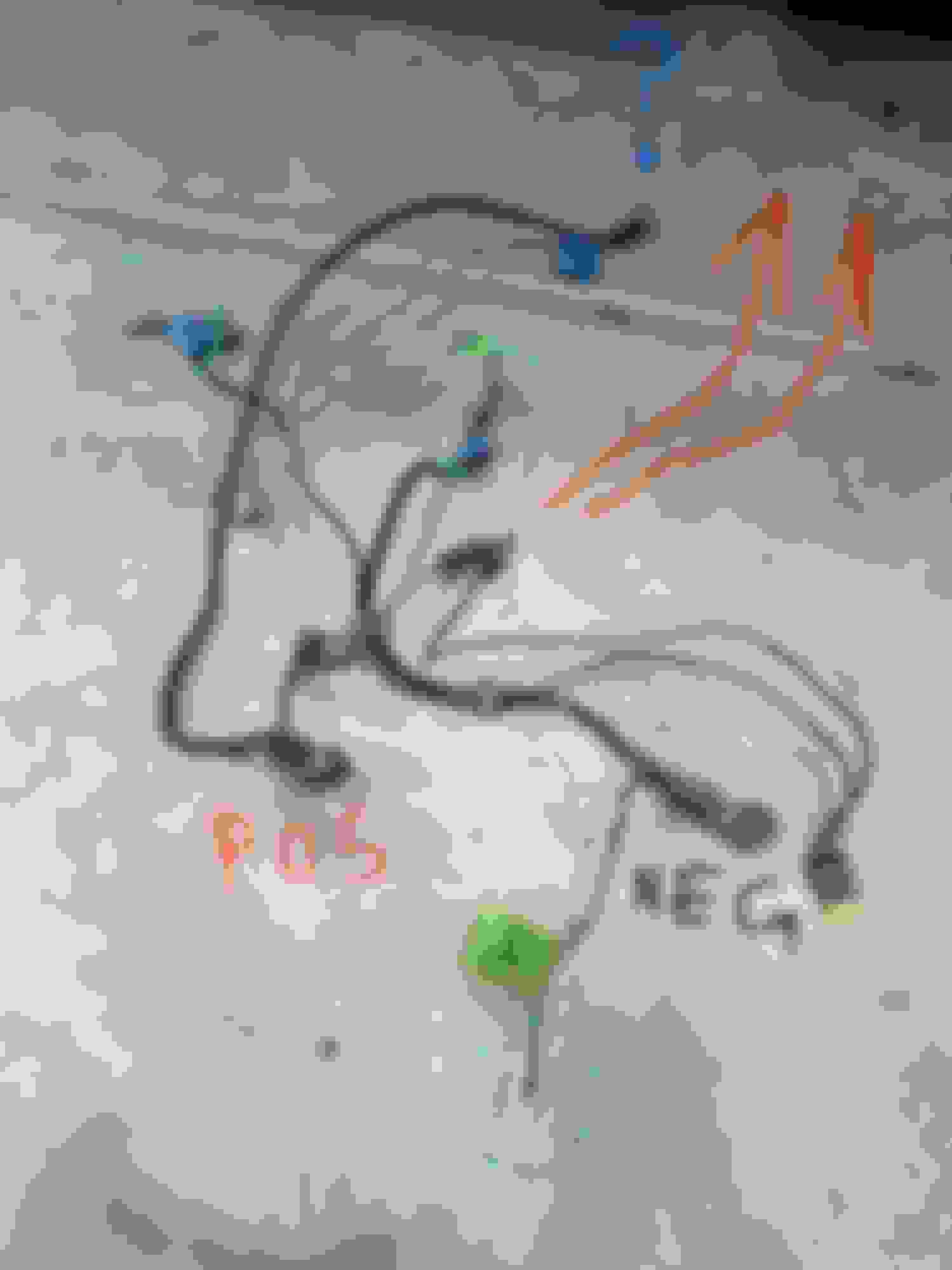
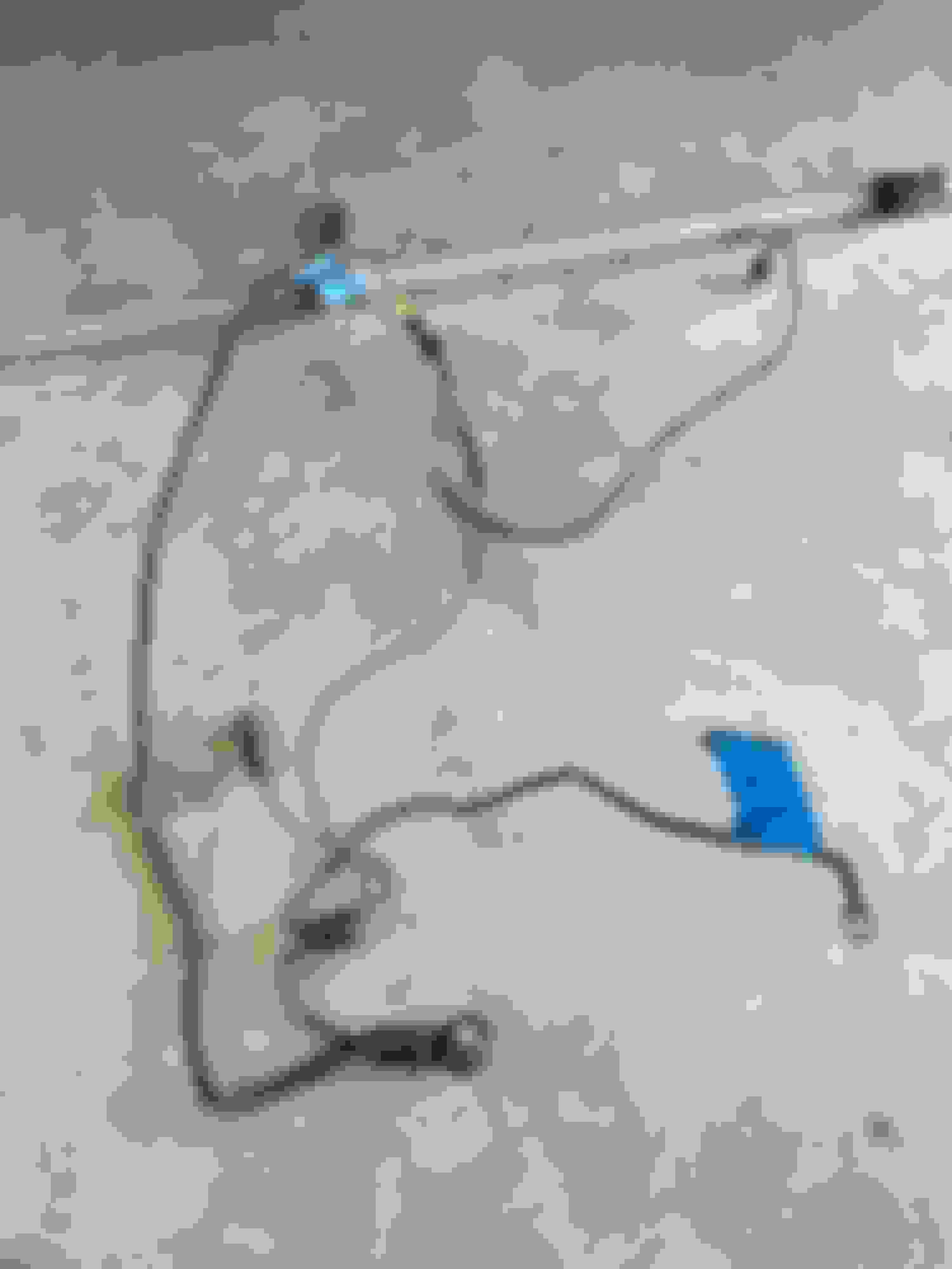
Here are 2 pics I found from when I pulled the engine. The wires are all intact.
The metal tube with wires in it resting on the K-member and steering was, I think, also connected to the starter. I’ll definitely take better pics tomorrow.
I recommend pay close attention to the alternator wiring, how it feeds back through a fuse to the battery. And make sure you research the type of alternator you plan to run, compare it with whatever the wiring is in the car now, as now is your chance to correct any wire issues related to the alternator. My gen3 LS engine for example uses a 1-wire and there is a choice of using the ECU to provide the regulation or we can choose to use the in-car lamp bulb. Gen4 alternators use 2-wires though, irrc, its a bit different. You may need to do some re-pinning somewhere. Its just things like this are best to sort out while everything is hanging out there where you can get to it, instead of after the engine is sitting on top of the harness.
If you are not using OEM accessories I would recommend one of the belt setups that places the alternator up high on the driver side, as opposed to down low like a OEM Camaro spacing. The low position of Camaro spacing also uses a camaro specific alternator support bracket, whereas the higher up one seems more favorable to the truck alternators which tend to be almost twice as powerful and more desirable than the camaro alternator and won't work with the aux bracket on the low oem position. It can still be used without the aux bracket but I question the reliability at high RPM and not willing to risk, personally.
The wires at the bottom of that picture with the blue tape were both attached to the solenoid. Those come from the body harness along with all the lights. Not sure why that one red cable is clipped, nor do I know where it went. This was disassembled 10 years ago!
This is the negative battery cable end.
One end went to the front of the alternator, and the other ground on the wheel well.
This is the positive side.
The 2 small wires coming out of that black cylinder tumor looking thing (I do need an actual name for this part) were both going to the ECU. The thick cable ran to a bolt on the solenoid. And the medium sized cable ran to the back of the alternator.
Here is my Gen III F-body alternator. 4 pin.
I went with the low, driver side mount. But I will be adding the support bracket to it.
Also, this is where the other cable come out of the firewall.
The smaller of the two runs to all the front lights. The only other wire there is that peach one sticking out by itself. It runs to the brake proportioning valve.
The bigger one has the cables/wires that tun to the solenoid, a coolant temperature sensor, the wiper assembly (which I no longer have) and a couple other ends that I didn’t label.
Does anyone know what that wiring assembly is called specifically? If so, I can look it up and trace the wires. Thanks.
Does anyone know what that wiring assembly is called specifically? If so, I can look it up and trace the wires. Thanks.
That is the C100 bulkhead. As mentioned, it has two harnesses. Headlight being one, and gages and such on the other. Plenty of info on this site to search for exact pin outs.
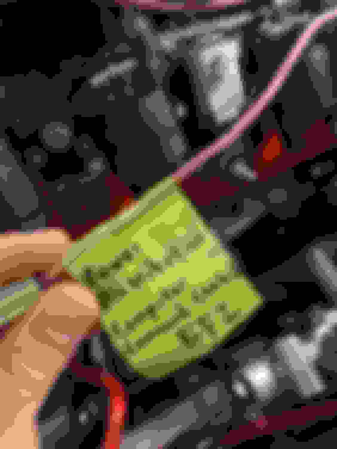
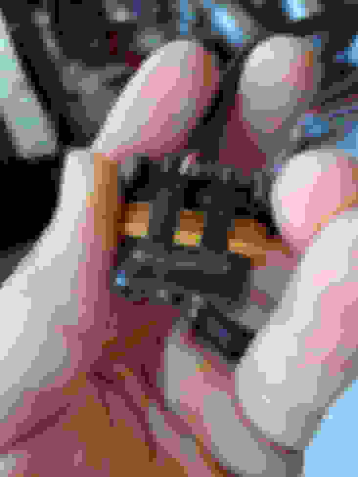
This little cylinder with “20” on it. It was coming off of the Positive cable and has 2 wires going to the ECU. I need a part name and description, what it does and such, so I can buy new battery cables and get everything set up properly.
That cylinder is a fusable link. Should there be a short, It will blow protecting the smaller wires in that assembly. It is a simple in line fuse. Commonly found in these cars (ignition system, starter, etc).
The Ground connections are actually the MOST important portion of the Vehicle's Electrical System.
Just a few notes for you on this:
-Make your new Negative Battery Cables from 4AWG or 2AWG Welding-Cable (The Positive Cable as well).
-The Battery Negative Post should have 2 Negative Cables attached.
(1 Cable will connect to the Engine Cylinder-Block ONLY, the 2nd Cable will go to a very clean Chassis location).
-The other side of the Engine Cylinder-Block will need another 4AWG or 2AWG Cable connected to another clean Chassis location.
-Not required for a Stock type Alternator, But I recommend another 4AWG or 2AWG Cable connected from the Body of the Alternator to the Bolt that attaches the Negative Battery Cable to the Engine Cylinder-Block (Battery to Block and the same attachment-point to the body of the Alternator).
Your Swap PCM should also have the Main Ground Connection attached directly to the Negative Battery Post.
(using a dedicated 10AWG Wire that attaches to NOTHING else).
Your Swap PCM should also have the Main 12V Positive Connection attached directly to the Positive Battery Post.
(AGAIN: using a dedicated 10AWG Wire that attaches to NOTHING else).
On to the next question. This cable coming out of the fusible link…
As you can see, it’s labeled “back of alternator”. Is this a ground? Coming off of the positive end of the battery cables?
Wow that is weird. It sure looks like a ground to me, but what the hell its going near the power cable through a fuse?
The power feed coming off the alternator usually goes into the fuse box, through a fuse, to some kind of lug. So I am tempted to say, since I don't see any fuse box or lug, and the wire looks pretty thin, it must be a ground huh? Just a guess.
My advice is figure out which wire comes off the alternator POWER lug, and goes to the fuse box to some lug or whatever through a fuse (probably a big fuse 60amp or 100amp or something) and then UPGRADE that wire. I used 4ga I think. But I also relocated my fuse box to the trunk, so larger wire diameter is needed for reduced current drop at some distance. Voltage is like water pressure through a pipe, it drops with distance based on friction with the walls of the pipe, so larger pipes = less friction = less pressure drop (less voltage drop)
Ya it has to be a ground. My guess is that, since it’s coming out of that fusible link, if there’s a short, the link blows and the short goes through there to ground so as to save the ECU. But who knows. Anyone else feel free to chime in.
Engine is in and mounted. Now I’ve begun the wiring process. I started with the ground straps that came with the PSI harness.
Here, there is a ground from block to firewall/chassis and block to head.
Here is the ground from head to head. I went in the front because I have no accessories on the heads. And it was easier to access than the back. I can always move it if need be.
And here is the large ground strap from block to frame.
Now I have to drill a hole in the firewall for the wiring harness, lay it all out, and let the good times roll. 😬
Paint is an insulator. Make sure all the paint is removed from the face of the boss where the ground strap is attached to engine block. Metal on metal contact. Same goes for frame or anywhere a ring terminal is attached. The bolt is there just to hold things tight together and the threads are not supposed to be relied on as the ground path. If you rely on the bolt thread then it'll work when new but not so much as things age.
That ground strap from engine block is actually the most important as it carries the high current of the starter. Route it straight to battery B-. Make sure that's a damn good ground so starter current isn't forced to take another route and end up melting smaller ground wires somewhere else in your electrical system.
I honestly recommend removing all the Original Ground Connections from the Car.
They are the most Important portion of the Electrical System.
Only Ground Connections should be:
-#1 Battery to Cylinder-Block (Not a Cylinder Head) Opposite side of the Starter Motor (this Cable does NOT touch the Chassis or any other Connection).
-#2 Opposite side of the Cylinder-Block (near the Starter Motor) to the Chassis, (No where else, no other connection).
-#3 Battery to Chassis (No where else, no other connection).
Something That I always NOW do, that I used to make Optional:
-#4 Alternator Body to the #1 Connection on Cylinder Block.
Optional/ Special use:
-"A" Ground Strap from #1 Connection on Cylinder Block to Transmission Case.
-"B" Smart Coils Ground to corresponding Cylinder Head.
-"C" Interior Electronics (NOT Electrical) may have a dedicated Cable from the Battery to a Ground Dist. Stud in the Cabin.
Last edited by vorteciroc; 07-30-2022 at 06:07 PM.
As you can see, it’s labeled “back of alternator”. Is this a ground? Coming off of the positive end of the battery cables?
Guys, that is NOT a Ground Connection, to the Alternator.
Think about what you are looking at...
That is the Positive Battery Cable!
Making that Connection, the POSITIVE Connection to the Alternator.
There is NO possible way for it to be a Ground Connection.
You would be surprised just how many Businesses are in that Market...
and have NO IDEA how the Electrical System actually operates.
...They probably think that Electricity (DC) (Electrons) flow from Positive to Negative!
LMAO!
When Electrons, or anything Negatively Charged, are attracted to a Negative Pole...
I will give away all of my assets and everything that I own.
Also, I sanded and ground down all metal spots where the ground connections would be made. There is no paint, rust or corrosion in any of those locations.
Depends what is the topic matter. You never know who you're talking to on these forums.
So you’re saying that, even though they specified how the ground straps should be placed, they might not know what they’re talking about? The way I see it, the grounds are important. You can’t be too cautious. But you can go overboard. Which I certainly don’t think this is.
With that being said, I’m certainly no expert. I’ll definitely listen to any and all advice given with an open mind. So thanks everyone for the input.
So you’re saying that, even though they specified how the ground straps should be placed, they might not know what they’re talking about?
I'm saying there are people here freely giving you better advice.
Spotting good advice is easier when you're fairly good with a topic matter. I'm truly in awe of the breadth of knowledge that vorteciroc has. It's kind of like the old TV commercials....
I also need to know the “function” of a couple wires from the C100.
This pink wire, F4
that’s what it is labeled as. But what does it do? Is it a “key on hot” wire for the ECU?
And there’s also a brown wire, F8, labeled “Charging system” but there is no further description. And I honestly don’t remember what it was originally connected to.
I could really use some guidance with these.
And I still need an answer about our brake pedals if they are “2 position” brake switches.
#1
The Alternator (Unless "Self-Exciting") will require use of that Brown Wire at the F8 Position of the C100 Connector...
It must connect to the Original Instrument Panel Cluster "Low Battery Voltage" Indicator-Lamp Bulb...
Or to an appropriate 470 Ohm 0.500 Watt Resistor.
Otherwise you will damage the Internal Voltage Regulator of the Alternator.
#2
If you are building/ configuring your own UBEC (Power Distribution Center) for Fuses and Relays...
The 10AWG Pink Wire at the F4 Position of the C100 Connector...
Is great for a Positive Trigger for Relays, on any Circuits that you want to Power with the Ignition-Switch Turned-On.
Last edited by vorteciroc; 09-21-2022 at 11:28 PM.
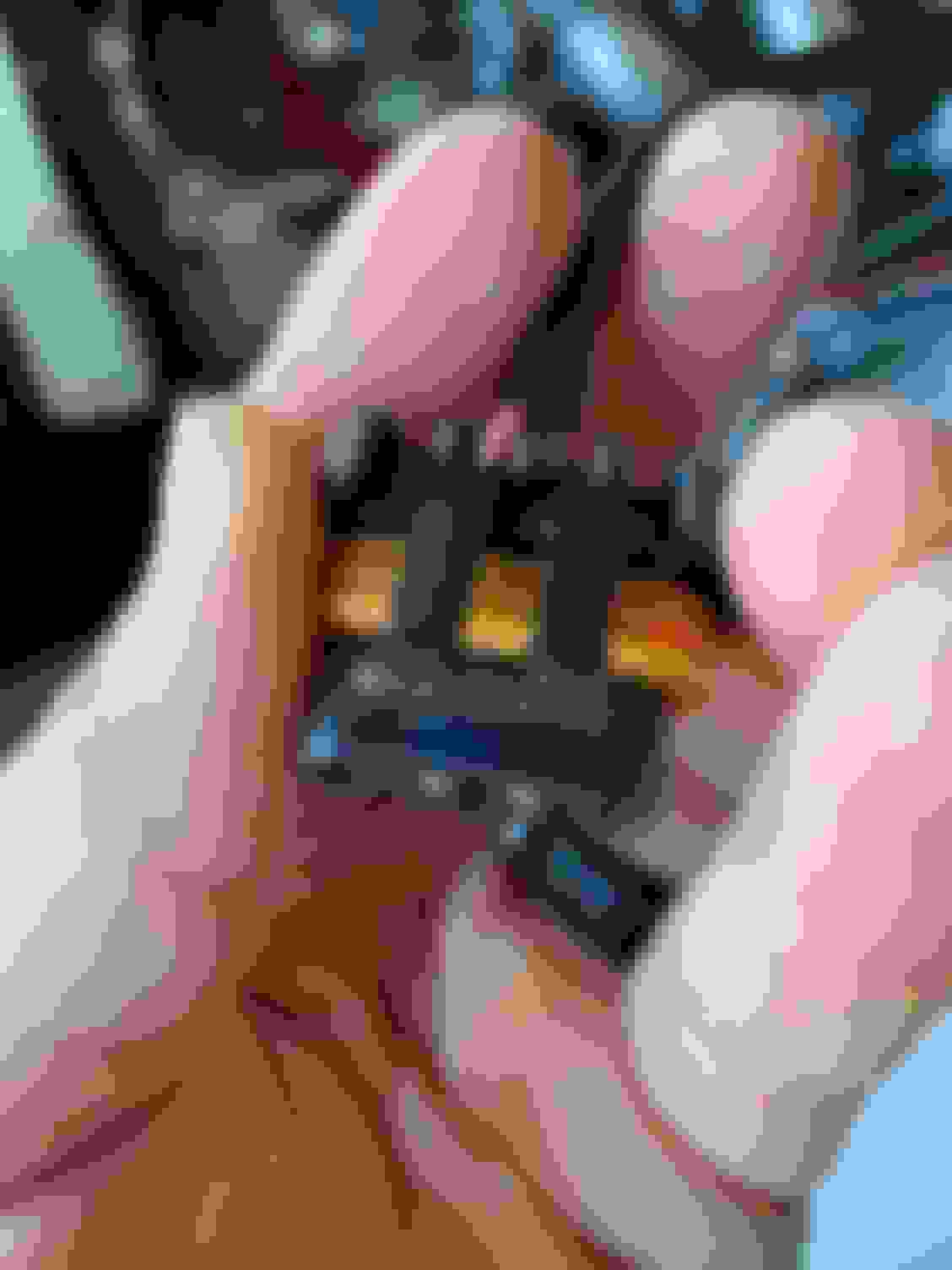
Thank you vorteciroc! Here’s the alternator I got.
Not sure if it’s “self exciting” or not.
But the PSI harness plugs directly into it. How would I incorporate that wire into the L pin? Do I not use it? Does the new ECU control that?
And yes, I am going to be running a small power distribution box for my fan relays. Good to know!
But there are indeed 2 pink wires coming from the C100. One is dark pink and runs to the small solenoid bolt on the starter. The other is that one that I have labeled with green tape.
The Alternator that you Posted (Summit Racing #810354) is NOT self-exciting.
Also...
That Model (the CS130-D) tends to overheat (the Bridge Rectifier) and needs HELP with cooling (but NOT as badly as the Non-D CS130).
You will notice that the Rear Cover used on this Model, has a provision for Cooling Ducting to be used.
I highly recommend connecting some type of Cooling Ducting to it!
If you are still shopping for an Alternator...
I would go with the AD230 instead.
Last edited by vorteciroc; 09-25-2022 at 06:21 PM.
Pay attention to the Brown Wire in the Image above.
The Brown Wire in the Image below, needs to T into the Brown Wire from Above:
This is the Wire that goes to the F8 Position of the C100 Connector (the one I spoke of in Post #37 and #38).
Last edited by vorteciroc; 09-27-2022 at 03:01 PM.
The F5 Position of the C100 Connector is used for different purposes depending on the Original Engine/ Transmission Option...
and the Sub-Model (Sport-Coupe, Berlinetta, Z28, Etc).
Most of the Time, it is used for the Circuit between an Engine Coolant Temperature Sending-Unit, and the corresponding Gauge (IPC).
If this is the case for your Vehicle:
You can confirm this by Testing for Continuity, on the Dark-Green wire at the Ignition Switch Connectors (turn Key to ON Position).
The Black Electrical Connector of the Ignition Switch will have 1 Terminal with 1 or 2 Dark Green Wires.
(This is where 1 end of the Multi-Meter Leads go... the other end goes to your mystery Dark Green Wire)
The Image below shows the Ignition Switch Connectors (and Wires):
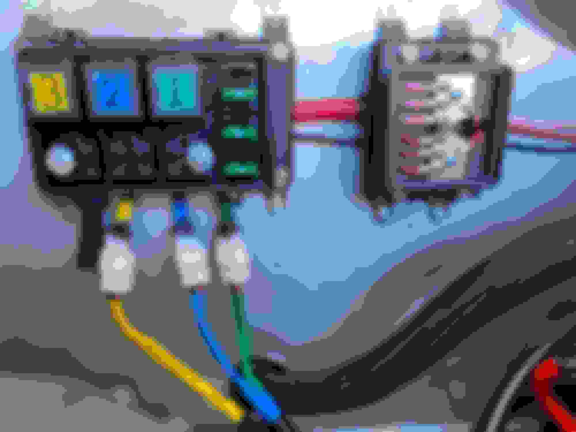
I’ve been working on the fan wiring for quite some time now. I’m mostly done with it.
Fan 1 is the radiator fan closest to the coolant inlet and outlet, set to go on at 195. Fan 2 is the second radiator fan set to go on at 205. Fan 3 is for the trans cooler and will run constantly while the car is on and running. I color coded all 3 at each end so there will be no confusion.
The wires are also loomed and routed nicely.
The only wires I need in the engine bay are the 2 ground triggers from the ECU for the radiator fans, and the 4 wires from the C100. Then I still have to wire the fuel pump, TCC, brake switch, and speedometer under the dash and mount the ECU.

 04-19-2022, 03:51 PM